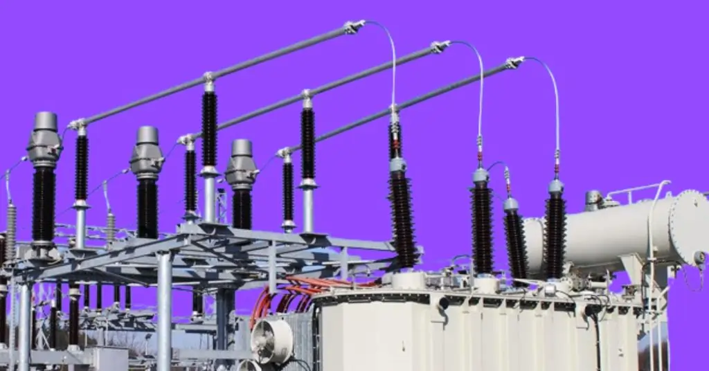
Instrument Transformers
Instrument transformers are critical components in modern electrical systems, serving the dual purpose of measuring electrical quantities and providing protection. These transformers are designed to accurately step down high voltage and current levels to safer, manageable metering and relay protection values. By doing so, they play a vital role in ensuring the safety, efficiency, and reliability of electrical grids and various industrial applications.
Understanding instrument transformers is essential for anyone involved in the electrical industry, from engineers to technicians. Their ability to isolate measuring instruments from high-voltage circuits protects equipment and ensures precise measurements. This blog post will delve into seven of the most amazing facts about instrument transformers, explore the different types and their specifications, and discuss their diverse applications and uses. Whether you’re looking to enhance your knowledge or make informed decisions for your electrical systems, this guide will provide valuable insights into the indispensable world of instrument transformers.
General Information
What are Instrument Transformers?
Instrument transformers are specialized electrical devices used to transform current and voltage levels from high values to lower, measurable values. These devices are essential for accurate metering, control, and protection in electrical systems. By stepping down the high voltage and current to lower, safer levels, they enable precise monitoring and measurement, ensuring the efficiency and safety of the electrical grid.
Purpose and Role in Electrical Systems
The primary purpose of instrument transformers is to provide accurate measurements of electrical parameters and to protect measuring instruments from the high voltage and current present in power systems. They play a crucial role in:
- Ensuring safety by isolating measurement instruments from high-voltage circuits.
- Providing accurate data for metering and billing purposes.
- Enabling the protection of power systems by supplying reliable data to protective relays.
- Facilitating the control and monitoring of electrical power distribution and consumption.
Key Components and Functions
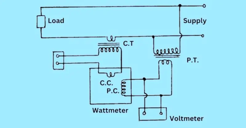
- Supply:
- The source of electrical power that the instrument transformer is connected to. This could be a high-voltage line or a busbar in a substation.
- Load:
- The end point where the transformed and measured electrical power is used. It can be any electrical device or system that consumes the electrical energy.
- Potential Transformer (P.T.):
- Function: Steps down high voltage to a lower, standardized voltage level that can be safely measured by meters and protective relays.
- Key Component: Consists of primary and secondary windings, where the primary winding is connected to the high-voltage circuit and the secondary winding to the measuring instruments.
- Current Transformer (C.T.):
- Function: Reduces high current levels to lower, measurable values and provides isolated current signals proportional to the current in the primary circuit.
- Key Component: Composed of a primary winding, secondary winding, and magnetic core. The primary winding is connected to the main current-carrying conductor, and the secondary winding is connected to measuring instruments or protective relays.
- Compensation Capacitor (C.C.):
- Function: Used in combination with transformers to correct power factor or to stabilize the voltage in the circuit.
- Key Component: Connected parallel to the load, it helps in improving the efficiency of the power system by reducing reactive power.
- Potential Coil (P.C.):
- Function: Used in voltmeters and wattmeters to measure voltage accurately.
- Key Component: A coil connected across the voltage to be measured, ensuring precise voltage readings by generating a magnetic field proportional to the voltage.
- Wattmeter:
- Function: Measures the power consumption in an electrical circuit.
- Key Component: Consists of current and potential coils that interact to produce a reading proportional to the power being used. The current coil is connected in series with the load, while the potential coil is connected parallel to the supply voltage.
- Voltmeter:
- Function: Measures the voltage across a component or a circuit.
- Key Component: Connected across the points where voltage needs to be measured, using a potential transformer for high-voltage circuits to step down the voltage to a safe level for measurement.
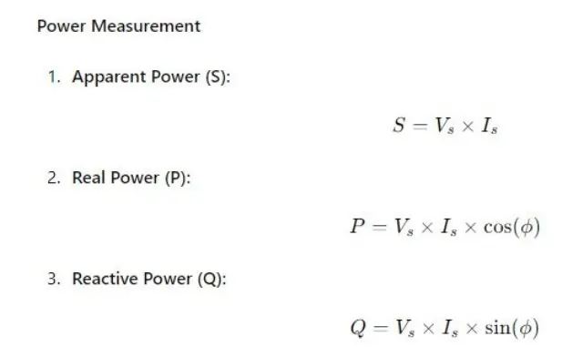
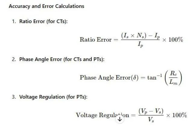
Important Formulas for Instrument Transformers
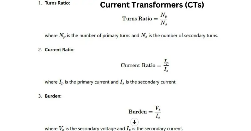
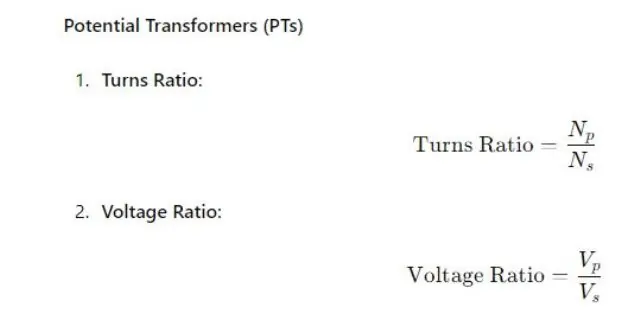
Types and Specifications
Current Transformers (CTs)
| Aspect | Description |
|---|---|
| Overview and Purpose | Current Transformers (CTs) are used to step down high current levels to lower, measurable values. They provide isolated current signals proportional to the current in the primary circuit, enabling accurate metering and protection of electrical systems. |
| Specifications and Ratings | Primary Current (Ip): The maximum current that the CT can handle on the primary side. Secondary Current (Is): Typically standardized to 5A or 1A. Burden: The load (in VA) connected to the secondary side of the CT. Accuracy Class: Defines the CT’s accuracy, e.g., 0.1, 0.2, 0.5, 1.0. Frequency: The operating frequency range, typically 50 Hz or 60 Hz. |
| Selection Criteria | Primary and Secondary Current Ratings: Choose based on the current levels in the system. Burden Rating: Ensure the CT can handle the connected load. Accuracy Class: Select according to the required measurement precision. Frequency Compatibility: Match with the system’s operating frequency. |
Potential Transformers (PTs)
| Aspect | Description |
|---|---|
| Overview and Purpose | Potential Transformers (PTs) are used to step down high voltage levels to lower, standardized voltage levels. This allows for safe and accurate voltage measurements and ensures the protection of measuring instruments. |
| Specifications and Ratings | Primary Voltage (Vp): The maximum voltage that the PT can handle on the primary side. Secondary Voltage (Vs): Typically standardized to 110V or 120V. Accuracy Class: Defines the PT’s accuracy, e.g., 0.1, 0.2, 0.5, 1.0. Burden: The load (in VA) connected to the secondary side of the PT. Frequency: The operating frequency range, typically 50 Hz or 60 Hz. |
| Selection Criteria | Primary and Secondary Voltage Ratings: Choose based on the voltage levels in the system. Accuracy Class: Select according to the required measurement precision. Burden Rating: Ensure the PT can handle the connected load. Frequency Compatibility: Match with the system’s operating frequency. |
Applications of Instrument Transformers
Residential Applications
Instrument transformers are rarely used in typical residential settings due to the lower voltage and current levels. However, they may be found in large residential complexes or apartment buildings where electrical loads are higher, requiring accurate metering and safety measures.
Commercial Applications
In commercial settings, instrument transformers are crucial for:
- Metering: Accurate measurement of electricity consumption for billing purposes in office buildings, shopping centers, and other commercial establishments.
- Energy Management: Monitoring and managing energy usage to optimize efficiency and reduce costs.
- Safety: Providing isolation and protecting low-voltage equipment from high-voltage systems.
Industrial Applications
In industrial environments, instrument transformers are essential for:
- Large Equipment Monitoring: Ensuring accurate measurement of current and voltage in heavy machinery and industrial processes.
- Control Systems: Feeding precise measurements into control systems to maintain operational efficiency.
- Power Distribution: Safeguarding the power distribution network within factories and large industrial plants.
Utility Settings
Instrument transformers play a vital role in utility settings, including:
- High Voltage Transmission: Stepping down high voltages and currents for safe measurement and monitoring in substations.
- Grid Management: Enabling the monitoring and control of electrical grids to ensure reliable power supply and distribution.
- Fault Detection: Identifying and isolating faults quickly to maintain the stability of the power grid.
Metering Systems
Instrument transformers are integral to metering systems, providing:
- Accuracy: Ensuring precise measurements of electrical parameters for billing and energy audits.
- Isolation: Protecting metering equipment from high voltages and currents.
- Scalability: Allowing for the measurement of a wide range of voltages and currents by scaling down to manageable levels.
Protection Systems
In protection systems, instrument transformers are critical for:
- Relay Protection: Supplying accurate current and voltage data to protective relays to detect and isolate faults.
- System Stability: Maintaining the stability of electrical systems by ensuring protective devices operate correctly.
- Safety: Enhancing the safety of electrical systems by preventing damage to equipment and reducing the risk of electrical hazards.
Installation and Usage
Step-by-Step Installation Guide
- Planning and Preparation:
- Site Survey: Conduct a thorough survey of the installation site to ensure it meets all safety and technical requirements.
- Select Equipment: Choose the appropriate instrument transformers (CTs or PTs) based on the system specifications and requirements.
- Gather Tools: Assemble all necessary tools and safety equipment for the installation process.
- Installation of Current Transformers (CTs):
- Mounting: Securely mount the CTs on the primary conductor, ensuring proper alignment.
- Primary Connections: Connect the primary side of the CTs to the high-current carrying conductors.
- Secondary Connections: Connect the secondary terminals to the metering or protective devices using appropriate wiring and ensuring proper polarity.
- Installation of Potential Transformers (PTs):
- Mounting: Install the PTs in a stable and secure location, typically on a panel or a mounting bracket.
- Primary Connections: Connect the primary side of the PTs to the high-voltage line, ensuring proper insulation and safety measures.
- Secondary Connections: Connect the secondary terminals to the measuring instruments or protective relays, ensuring proper polarity and grounding.
- Testing and Calibration:
- Initial Testing: Perform initial testing to ensure all connections are secure and the transformers are functioning correctly.
- Calibration: Calibrate the transformers as per the manufacturer’s specifications to ensure accurate measurements.
- Safety Checks:
- Inspection: Conduct a final inspection to verify all connections, mounting, and safety measures.
- Documentation: Record the installation details, including the transformer ratings, connections, and calibration settings.
Best Practices for Usage
- Regular Maintenance: Schedule regular maintenance checks to ensure the transformers are functioning correctly and to identify any potential issues early.
- Proper Load Management: Ensure that the connected load does not exceed the rated burden of the transformers.
- Accurate Metering: Regularly calibrate the metering equipment connected to the transformers to maintain accuracy.
- Monitoring: Continuously monitor the performance of the transformers and the connected systems to detect any anomalies.
Common Pitfalls to Avoid
- Incorrect Polarity: Ensure that the polarity markings are correctly followed during installation to avoid inaccurate measurements and potential system faults.
- Overloading: Avoid connecting loads that exceed the transformer’s rated capacity, as this can lead to overheating and failure.
- Poor Connections: Ensure all electrical connections are tight and secure to prevent arcing, which can damage the transformers and connected equipment.
- Lack of Regular Maintenance: Neglecting regular maintenance can lead to undetected issues, reducing the lifespan and reliability of the transformers.
- Improper Grounding: Ensure proper grounding of the transformers to prevent electrical shocks and improve safety.
Safety and Standards
| Aspect | Description |
|---|---|
| Safety Standards and Certifications | IEC 61869: International standard for instrument transformers, ensuring safety and performance. ANSI/IEEE C57.13: Standard for requirements, application, and testing of instrument transformers in the United States. ISO 9001: Certification for quality management systems, ensuring consistent product quality and safety. |
| Ensuring Accuracy in Measurements | Calibration: Regularly calibrate instrument transformers to maintain measurement accuracy. Testing: Conduct routine testing to detect any deviations or faults. Environmental Factors: Consider temperature, humidity, and other environmental factors that can affect accuracy and compensate accordingly. |
| Importance of Compliance with Standards | Safety: Compliance with standards ensures the safe operation of instrument transformers and the protection of personnel and equipment. Reliability: Adhering to standards guarantees reliable performance and longevity of the transformers. Regulatory Compliance: Meeting international and local standards helps in adhering to legal and regulatory requirements, avoiding penalties and legal issues. |
Troubleshooting and Maintenance
| Aspect | Description |
|---|---|
| Common Issues and Their Solutions | Issue: Inaccurate measurements Solution: Check and calibrate the instrument transformers regularly. Replace if necessary. Issue: Overheating Solution: Ensure proper ventilation and avoid overloading the transformers. Check for any blockages or cooling system failures. Issue: Insulation failure Solution: Regularly inspect and maintain insulation. Replace damaged insulation immediately. Issue: Loose connections Solution: Tighten all electrical connections and inspect them periodically to prevent arcing and failures. |
| Regular Maintenance Tips | Visual Inspection: Perform regular visual inspections to identify any obvious signs of wear and tear, such as discoloration, cracks, or leaks. Cleaning: Keep the transformers and surrounding areas clean from dust and debris to ensure optimal performance and prevent overheating. Testing and Calibration: Conduct periodic testing and calibration to ensure accuracy and detect any deviations early. Lubrication: Ensure all moving parts, if any, are properly lubricated to reduce wear and extend the life of the transformers. |
| Ensuring Longevity and Reliability | Quality Installation: Ensure the transformers are installed correctly according to manufacturer guidelines and industry standards. Environment Control: Maintain a controlled environment, including temperature and humidity levels, to prevent adverse effects on the transformers. Load Management: Avoid overloading the transformers by ensuring that the connected loads do not exceed the rated capacity. Proactive Repairs: Address any issues immediately upon detection to prevent them from escalating into more serious problems. |
Comparisons and Reviews
| Aspect | Description |
|---|---|
| Top Brands and Models | ABB: Renowned for high-quality and reliable instrument transformers. Models include ABB KEVA, ABB PVA. Siemens: Offers a wide range of CTs and PTs known for durability. Notable models are Siemens 3VL, Siemens SENTRON. GE Grid Solutions: Known for precision and performance. Key models include GE PCT200, GE JKV. Schneider Electric: Provides versatile and efficient solutions. Popular models are Schneider Electric TRIHAL, Schneider VAMP. |
| Performance and Accuracy Comparisons | ABB: High accuracy and consistent performance, suitable for critical applications. Siemens: Excellent performance with robust design, slightly higher price point. GE Grid Solutions: Superior accuracy with advanced technology, mid-range cost. Schneider Electric: Balanced performance and cost, reliable for various applications. |
| Durability and Value for Money | ABB: High durability, excellent long-term investment despite higher initial cost. Siemens: Very durable, justifies higher cost with long lifespan and reliability. GE Grid Solutions: Good durability, offers value with advanced features and moderate pricing. Schneider Electric: Reliable durability, offers good value for money with balanced pricing and performance. |
| User Reviews and Expert Opinions | ABB: Users appreciate the reliability and accuracy, experts highlight its suitability for critical applications. Siemens: Positive user feedback on durability, experts commend the robust design and performance. GE Grid Solutions: Users and experts praise the precision and advanced features, seen as a good mid-range option. Schneider Electric: Users value the balance of cost and performance, experts recommend it for diverse applications. |
Cost and Procurement
| Aspect | Description |
|---|---|
| Pricing Information | ABB: Typically ranges from $500 to $2000 depending on specifications and model. Siemens: Price range is around $600 to $2500, higher for specialized models. GE Grid Solutions: Mid-range pricing, approximately $700 to $2200. Schneider Electric: Generally priced between $550 and $2100, depending on the model and features. |
| Procurement Processes | Requirement Analysis: Identify the specific needs and specifications based on the application. Budget Planning: Determine the budget based on pricing information and total cost of ownership. Supplier Research: Research and shortlist potential suppliers based on reliability and reviews. Request for Quotation (RFQ): Send RFQs to selected suppliers to get detailed pricing and terms. Evaluation and Selection: Compare quotes based on cost, specifications, delivery times, and after-sales support. Purchase Order (PO): Issue a PO to the chosen supplier and confirm delivery schedules. |
| Trusted Suppliers and Where to Buy | ABB: Purchase from authorized distributors like Graybar, Wesco, or directly from ABB’s website. Siemens: Available through suppliers such as Allied Electronics, Grainger, and directly from Siemens’ website. GE Grid Solutions: Can be bought from GE’s official distributors, Grainger, and directly from GE’s website. Schneider Electric: Available through Schneider’s authorized partners, Rexel, and directly from Schneider’s website. |
FAQ on “Instrument Transformers”
Q: What is the primary purpose of instrument transformers?
A: To step down high voltage and current for safe measurement and protection.
Q: What are the main types of instrument transformers?
A: Current Transformers (CTs) and Potential Transformers (PTs).
Q: Why is regular maintenance of instrument transformers important?
A: It ensures accuracy and reliability.
Q: How do instrument transformers enhance safety in electrical systems?
A: By isolating measuring instruments from high voltage circuits.
Conclusion
Instrument transformers play an indispensable role in the accurate measurement, control, and protection of electrical systems. By stepping down high currents and voltages to safer levels, they ensure the reliability and safety of power grids and various applications across residential, commercial, industrial, and utility settings. Understanding their types, specifications, installation, maintenance, and the importance of adhering to safety standards is crucial for optimizing their performance and longevity. Whether for metering, protection, or advanced technological integration, instrument transformers are vital components that enhance the efficiency and stability of our electrical infrastructure.
