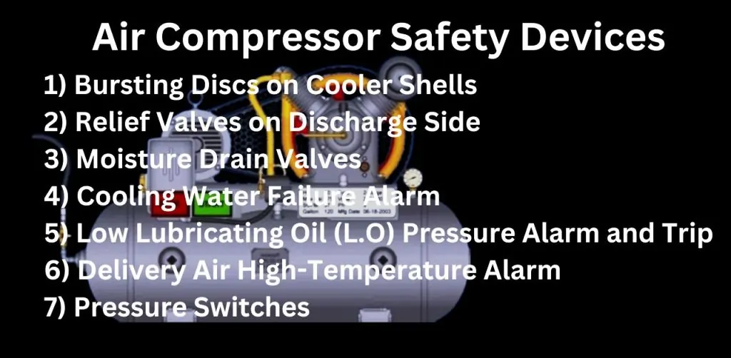
Air Compressor Safety Devices
Safety is a fundamental aspect of operating air compressors. Safety devices are crucial for protecting both your equipment and personnel from potentially dangerous failures. When these devices are properly maintained, they ensure your compressor runs efficiently, reducing the risk of accidents and avoiding costly downtimes or injuries. This post introduces the seven most critical safety devices that every air compressor should have. Each device plays a key role in safeguarding your operations, making regular maintenance essential for maintaining a secure and reliable working environment.
Bursting Discs on Cooler Shells (Water Side)
What is a Bursting Disc?
A bursting disc is a safety device designed to protect equipment from overpressure conditions. It is a thin, precisely engineered metal membrane that ruptures when the pressure exceeds a predetermined limit, thereby preventing damage to the equipment or potential safety hazards.
Application in Air Compressors
In air compressors, bursting discs are strategically fitted on the cooler shells at the water side. These discs are positioned to monitor and release pressure buildup within the cooling system. When the pressure reaches a critical point, the bursting disc ruptures, allowing the excess pressure to safely escape, thus protecting the compressor from potential overpressure-related damage.
Safety Formula: Overpressure Calculation
The bursting disc’s operation is based on the principle of pressure:
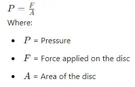
This formula helps in determining the exact pressure at which the disc will rupture, ensuring it activates only when necessary.
Importance
Bursting discs are vital in preventing catastrophic failures by acting as a last line of defense against overpressure. By rupturing at a critical pressure point, they safeguard the compressor, preventing equipment damage and ensuring the safety of the operating environment.
Relief Valves on Discharge Side for Each Stage
Role of Relief Valves
Relief valves are essential safety devices designed to release excess pressure from a system, preventing overpressure that could lead to equipment failure or safety hazards. These valves automatically open when the pressure within a system exceeds a preset limit, allowing the excess pressure to escape and thereby maintaining safe operating conditions.
Implementation in Multi-Stage Compressors
In multi-stage compressors, relief valves are strategically placed on the discharge side of each stage. This placement ensures that any overpressure in a specific stage is immediately relieved, protecting both that stage and the overall compressor system. By doing so, relief valves prevent localized pressure buildup, which could otherwise lead to mechanical damage or operational failure.
Safety Formula: Relief Valve Sizing
The sizing of a relief valve is critical to its effectiveness. The flow rate (QQQ) through a relief valve can be calculated using the following formula:
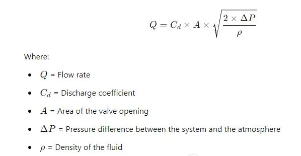
This formula ensures that the relief valve is appropriately sized to handle the expected pressure levels and flow rates, allowing it to function effectively when needed.
Criticality
Relief valves play a crucial role in preventing stage-specific overpressure, which can lead to significant damage if not controlled. By providing a controlled release of excess pressure, these valves protect the compressor from potential mechanical failures, ensuring safe and continuous operation across all stages.
Moisture Drain Valves (Unloader) on Cooler Sides
Purpose of Moisture Drain Valves
Moisture drain valves, commonly known as unloaders, are vital components in air compressor systems. Their primary function is to remove accumulated moisture from the air that is compressed and cooled. This moisture, if not properly drained, can cause corrosion and reduce the efficiency and lifespan of the compressor.
Placement in Air Compressors
In air compressors, moisture drain valves are strategically fitted at each cooler side. This placement ensures that moisture is effectively removed from the compressed air as it passes through the cooling stages. By regularly discharging moisture, these valves help maintain the integrity and performance of the compressor, preventing water buildup that could lead to operational issues.
Safety Considerations
Regularly draining moisture from the compressor system is crucial to prevent corrosion of internal components and to ensure that the compressor operates at peak efficiency. Failure to properly manage moisture levels can lead to rust, increased wear and tear, and ultimately, costly repairs or system failures.
Critical Formula: Drainage Rate Calculation
The drainage rate (Qd) of moisture from the system can be calculated using the following formula:
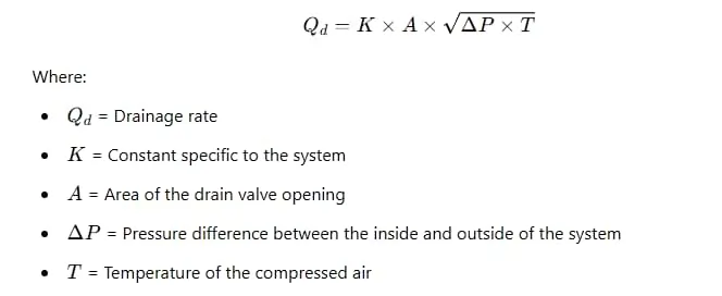
This formula helps in determining the appropriate size and capacity of the moisture drain valve to ensure effective moisture removal, maintaining the system’s efficiency and preventing potential damage.
Importance
Moisture drain valves are essential for preventing the detrimental effects of moisture on compressor systems. By ensuring regular and effective drainage, these valves contribute to the long-term reliability and efficiency of air compressors, making them an indispensable part of the overall safety and maintenance strategy.
Cooling Water Failure Alarm
Why Cooling Water is Vital
Cooling water plays a critical role in air compressor systems by regulating temperatures and preventing overheating. As compressors operate, they generate significant heat, which, if not properly managed, can lead to decreased efficiency, increased wear on components, and potential system failures. The cooling water circulates through the system, absorbing excess heat and maintaining optimal operating temperatures, ensuring the compressor functions smoothly and efficiently.
Alarm Systems
A cooling water failure alarm is designed to monitor the flow and temperature of the cooling water in real-time. If the system detects a drop in water flow or a rise in temperature beyond acceptable limits, the alarm is triggered. This alarm serves as an early warning system, alerting operators to potential cooling issues before they escalate into more serious problems, such as overheating or equipment failure.
Safety Mechanism
Upon activation of the cooling water failure alarm, immediate actions must be taken to prevent overheating and protect the compressor from damage. These actions typically include:
- Shutting down the compressor to stop further heat generation.
- Inspecting the cooling system for blockages, leaks, or pump failures.
- Restoring normal water flow or cooling functions before restarting the compressor.
By responding promptly to the alarm, operators can prevent significant damage to the compressor, avoiding costly repairs and ensuring the longevity and reliability of the system. The cooling water failure alarm is thus an essential safety mechanism, providing critical protection against the risks associated with inadequate cooling.
Low Lubricating Oil (L.O) Pressure Alarm and Trip
Importance of Lubrication in Compressors
Lubricating oil is essential in air compressors, playing a crucial role in minimizing friction between moving parts and reducing wear and tear on the machinery. Proper lubrication ensures that the compressor operates smoothly, with minimal resistance, thus extending the lifespan of the equipment and maintaining its efficiency. Without adequate lubrication, the compressor components would quickly deteriorate, leading to increased maintenance costs and potential system failures.
Alarm and Trip Functionality
The low lubricating oil (L.O) pressure alarm and trip system is designed to protect the compressor from operating under insufficient lubrication conditions. The system continuously monitors the oil pressure within the compressor. If the oil pressure drops below a critical threshold, the alarm is triggered, alerting operators to the issue. If the pressure continues to fall, the trip mechanism is activated, automatically shutting down the compressor to prevent damage. This dual-function system ensures that the compressor is not allowed to run without adequate lubrication, thereby protecting the equipment from severe damage due to metal-on-metal contact.
Safety Formula: Lubrication Rate Calculation
The lubrication rate (QL) can be calculated using the following formula:
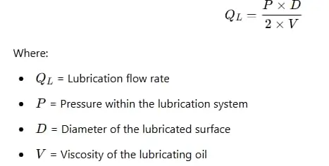
This formula helps in determining the correct flow rate of the lubricating oil necessary to maintain optimal performance of the compressor. By ensuring the lubrication system is functioning correctly and within the required parameters, the risk of damage due to inadequate lubrication is minimized.
Importance
The low L.O pressure alarm and trip system is a vital safety feature in air compressors, preventing the potentially catastrophic consequences of operating without sufficient lubrication. By automatically shutting down the compressor when oil pressure drops, this system ensures the longevity and reliability of the equipment, safeguarding against costly repairs and downtime.
Delivery Air High-Temperature Alarm on After Cooler Outlet
Temperature Monitoring
The high-temperature alarm system at the after cooler outlet is a crucial safety feature in air compressors. This system continuously monitors the temperature of the compressed air as it exits the after cooler. If the temperature rises above a preset limit, the alarm is triggered, alerting operators to potential issues that could compromise the efficiency and safety of the compressor. This early warning system is essential for maintaining optimal operating conditions and preventing overheating.
Critical Temperature Threshold
Maintaining the delivery air temperature below 93°C is critical for the safe operation of the compressor. Temperatures above this threshold can lead to several problems, including reduced air density, decreased compressor efficiency, and increased risk of damage to components. By monitoring and controlling the air temperature, operators can ensure that the compressor functions efficiently and safely, avoiding the complications associated with overheating.
Safety Formula: Heat Transfer Calculation
The heat transfer (Q) within the compressor system can be calculated using the following formula:
Q=m×Cp×ΔT
Where:
- Q = Heat transfer
- m = Mass flow rate of the air
- Cp = Specific heat capacity of the air
- ΔT = Temperature difference between the inlet and outlet of the after cooler
This formula helps in understanding how much heat needs to be removed to keep the air temperature within safe limits. It provides a basis for designing and maintaining cooling systems that can handle the heat generated during compression.
Consequences of High Temperature
Operating a compressor with delivery air temperatures exceeding 93°C can lead to severe consequences. High temperatures increase the risk of overheating, which can cause premature wear on compressor components, leading to frequent breakdowns and costly repairs. In extreme cases, overheating can result in fire hazards, putting both the equipment and personnel at risk. Therefore, it is vital to respond promptly to high-temperature alarms to prevent these dangers and maintain a safe working environment.
Additional Safety Devices
Pressure Switches
Pressure switches are essential components in air compressor systems, responsible for maintaining operation within safe pressure limits. These devices monitor the pressure levels within the compressor and automatically activate or deactivate the compressor to ensure it operates within the specified range. By preventing overpressure or underpressure conditions, pressure switches play a crucial role in protecting the compressor from damage and ensuring consistent and safe operation. Their ability to provide real-time feedback and control makes them indispensable in maintaining the overall safety and efficiency of the system.
Vibration Sensors
Vibration sensors are critical for detecting abnormal movements or vibrations in the compressor, which can indicate potential mechanical issues. These sensors continuously monitor the compressor’s vibration levels and trigger alarms or automatic shutdowns if they detect vibrations that exceed safe thresholds. By identifying problems early, such as misalignments, bearing failures, or unbalanced components, vibration sensors help prevent serious mechanical failures, reduce downtime, and extend the lifespan of the compressor. Implementing vibration sensors in a compressor system is an effective way to safeguard against unexpected breakdowns and ensure reliable operation.
Emergency Stop Button
An emergency stop button is a vital safety feature in any compressor system, designed to allow immediate shutdown in case of any malfunction or dangerous situation. Positioned in an easily accessible location, the emergency stop button provides a quick and effective way to halt the compressor’s operation, preventing potential accidents or equipment damage. In critical situations where every second counts, the ability to stop the compressor instantly can prevent injuries, minimize damage, and enhance overall workplace safety. The inclusion of an emergency stop button is not just a safety measure but a necessary component for ensuring a swift response to any unforeseen issues.
FAQ on “Air Compressor Safety Devices”
Q: What is the purpose of an air compressor’s relief valve?
A: To release excess pressure and prevent overpressure damage.
Q: Why is a high-temperature alarm important in an air compressor?
A: It alerts operators to overheating risks, preventing potential equipment damage.
Q: How do moisture drain valves enhance air compressor safety?
A: They remove accumulated moisture to prevent corrosion and ensure efficient operation.
Q: What is the function of an emergency stop button in air compressors?
A: It allows immediate shutdown in case of a malfunction or emergency.
Conclusion
In summary, the seven most critical safety devices for air compressors—bursting discs, relief valves, moisture drain valves, cooling water failure alarms, low lubricating oil pressure alarms, high-temperature alarms, and additional safety devices like pressure switches, vibration sensors, and emergency stop buttons—are essential for ensuring the safe and efficient operation of your equipment. Each of these devices plays a specific role in protecting your compressor from potential hazards and maintaining optimal performance.
Regular maintenance and vigilant monitoring of these safety devices cannot be overstated. By keeping these components in top condition, you not only prevent accidents but also avoid costly downtimes and extend the lifespan of your compressor system. Prioritizing safety through the proper upkeep of these devices is an investment in the reliability and efficiency of your operations.
Ultimately, the safety of your compressor system hinges on the effectiveness of these critical devices. By making their maintenance a priority, you ensure a safer work environment, reduce the risk of unexpected failures, and keep your compressor running smoothly for years to come.
