Bridge Rectifier
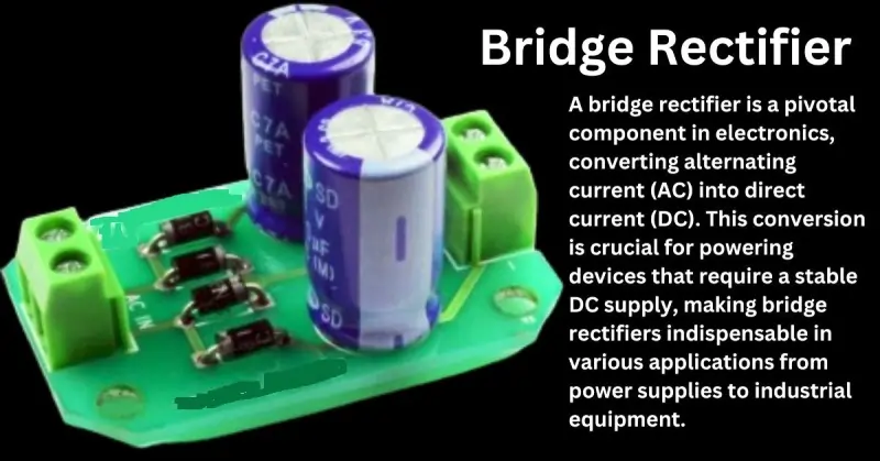
A bridge rectifier is a pivotal component in electronics, converting alternating current (AC) into direct current (DC). This conversion is crucial for powering devices that require a stable DC supply, making bridge rectifiers indispensable in various applications from power supplies to industrial equipment.
In this blog post, we will explore the basics of bridge rectifiers, starting with a definition and their importance in electronics. We’ll cover the basic operation and components, focusing on the roles of diodes and transformers within the rectifier circuit. Additionally, we’ll discuss different types of bridge rectifiers, such as single-phase and three-phase variants, and highlight their applications and advantages. You’ll learn about the working principles, including diagrams to illustrate the process, and discover common applications and real-world examples. We’ll also provide a step-by-step guide on designing and implementing a bridge rectifier circuit, troubleshooting tips, and explore recent innovations and future trends.
Types of Bridge Rectifiers
Single-Phase Bridge Rectifiers
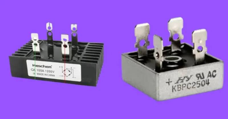
Single-phase bridge rectifiers are the most commonly used rectifiers in small-scale applications. They consist of four diodes arranged in a bridge configuration to convert single-phase AC input into a pulsating DC output. These rectifiers are known for their simplicity, ease of implementation, and cost-effectiveness. They are typically used in low to medium power applications, such as in household electronic devices, battery chargers, and small power supplies. The key characteristics of single-phase bridge rectifiers include moderate voltage regulation and ripple voltage, which can be managed using filtering techniques.
Three-Phase Bridge Rectifiers
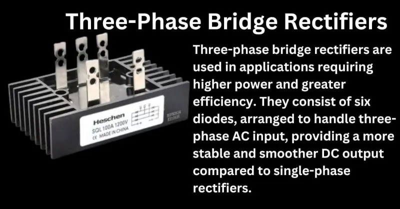
Three-phase bridge rectifiers are used in applications requiring higher power and greater efficiency. They consist of six diodes, arranged to handle three-phase AC input, providing a more stable and smoother DC output compared to single-phase rectifiers. The benefits of three-phase bridge rectifiers include reduced ripple voltage, improved voltage regulation, and higher power handling capabilities. They are commonly used in industrial applications, such as motor drives, large power supplies, and renewable energy systems like solar and wind power converters. These rectifiers are essential for environments where efficiency and reliability are critical.
Applications and Advantages
When comparing single-phase and three-phase bridge rectifiers, the applications and advantages of each type become clear. Single-phase bridge rectifiers are ideal for lower power applications where cost and simplicity are priorities. They are sufficient for everyday electronic devices and smaller power systems. In contrast, three-phase bridge rectifiers are better suited for high-power applications where efficiency, stability, and smooth DC output are crucial. The reduced ripple voltage and better voltage regulation of three-phase rectifiers make them the preferred choice for industrial and commercial applications. Additionally, three-phase rectifiers contribute to energy savings and improved performance in demanding environments.
Working Principle
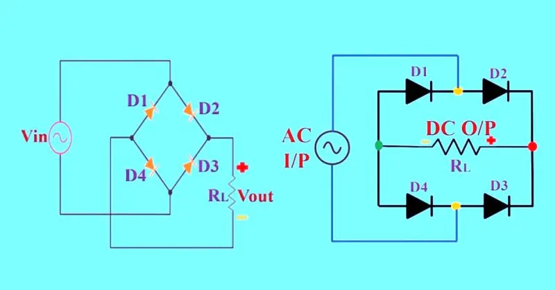
Detailed Explanation The working principle of a bridge rectifier involves converting alternating current (AC) into direct current (DC) using diodes arranged in a bridge configuration. This process ensures that the output voltage is unidirectional, making it suitable for powering DC devices.
Step-by-Step Breakdown of the Rectification Process
- AC Input: The AC voltage is supplied to the bridge rectifier circuit. This input voltage is typically a sinusoidal waveform alternating between positive and negative cycles.
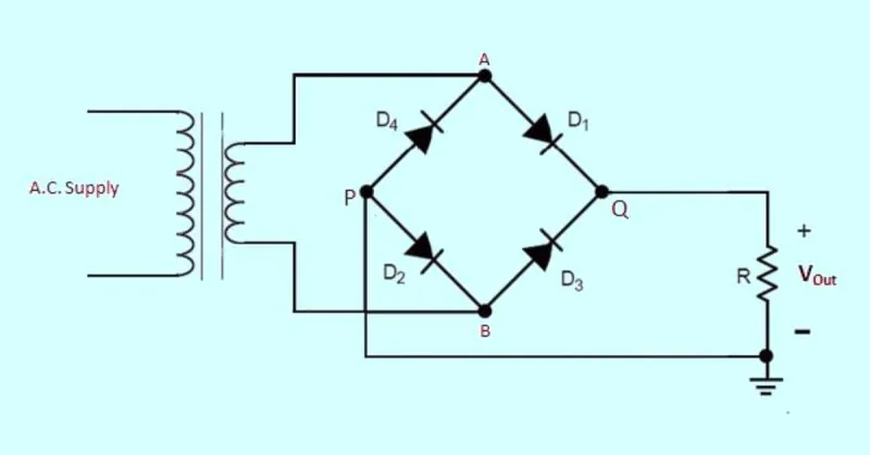
- Diode Configuration: The bridge rectifier consists of four diodes (D1, D2, D3, and D4) arranged in a bridge structure. These diodes direct the current flow during both positive and negative cycles of the AC input.
- Positive Half-Cycle:
- During the positive half-cycle of the AC input, diodes D1 and D2 become forward-biased (conducting), while diodes D3 and D4 are reverse-biased (non-conducting).
- The current flows from the AC source through diode D1, passes through the load resistor (R_L), and returns to the AC source via diode D2.
- This ensures that the load resistor experiences a positive voltage.
- Negative Half-Cycle:
- During the negative half-cycle of the AC input, diodes D3 and D4 become forward-biased, while diodes D1 and D2 are reverse-biased.
- The current flows from the AC source through diode D3, passes through the load resistor (R_L), and returns to the AC source via diode D4.
- This maintains the same direction of current flow through the load resistor, ensuring a unidirectional output.
- DC Output: The result of the rectification process is a pulsating DC voltage across the load resistor. While the current flow through the load remains unidirectional, the output voltage still contains ripples corresponding to the AC input frequency.
- Smoothing: To obtain a smoother DC output, a capacitor is often placed parallel to the load resistor. This capacitor charges during the peaks of the rectified output and discharges during the troughs, effectively reducing the ripple voltage.
Formulae to Support the Description
- Peak Output Voltage (V_peak):
- The peak output voltage of a bridge rectifier is slightly less than the peak input AC voltage due to the voltage drop across the diodes. Each conducting pair of diodes drops about 0.7V (for silicon diodes).

2. Average DC Output Voltage (V_DC):
The average output voltage of the bridge rectifier can be approximated using the peak output voltage:

Ripple Voltage (V_ripple):
The ripple voltage depends on the load resistance RLR_LRL, the frequency of the AC supply fff, and the capacitance CCC used for smoothing.

Applications
| Applications | Description |
|---|---|
| Common Applications | |
| Power Supplies | Bridge rectifiers convert AC voltage from the mains supply into DC voltage required by many electronic circuits. |
| Battery Charging | In battery chargers, bridge rectifiers convert AC voltage from the wall outlet into DC voltage suitable for charging batteries. Common in chargers for mobile phones, laptops, and other portable devices. |
| DC Motor Drives | Bridge rectifiers provide the necessary DC voltage for the operation of DC motors, commonly used in industrial machinery and electric vehicles. |
| Solar Power Systems | In solar power systems, bridge rectifiers convert AC voltage generated by inverters into DC voltage to store energy in batteries or to power DC loads. |
| Welding Equipment | Bridge rectifiers convert AC supply into DC output, essential for certain types of welding processes. |
| Real-World Examples | |
| Household Power Supply | Scenario: A typical household power supply unit requires a stable DC voltage to power various electronic devices. Application: Converts 120V or 240V AC from the wall outlet into a lower DC voltage, regulated for device use. |
| Electric Vehicle Charging Station | Scenario: EV charging stations need to convert AC mains supply into DC voltage to charge vehicle batteries. Application: Bridge rectifiers convert AC to DC, providing necessary DC voltage to the vehicle’s battery management system. |
| Solar Inverter System | Scenario: Solar inverter systems convert DC power from solar panels into AC power for household use. Application: Bridge rectifiers convert excess AC power back to DC for storage in batteries, maximizing efficiency and reliability. |
| Industrial Automation | Scenario: Industrial automation systems require precise DC power for sensors, controllers, and actuators. Application: Bridge rectifiers ensure AC power from mains is converted to required DC voltage, supporting automated production lines. |
Design and Implementation
Step-by-Step Guide
Designing a bridge rectifier circuit involves several key steps to ensure efficient and reliable operation. Here is a step-by-step guide:
- Determine Specifications:
- Identify the input AC voltage and frequency.
- Determine the desired DC output voltage and current.
- Calculate the required ratings for components based on these specifications.
- Select Diodes:
- Choose diodes with a peak inverse voltage (PIV) rating higher than the peak AC voltage.
- Ensure the diodes have a current rating exceeding the maximum load current.
- Choose a Transformer (if needed):
- Select a transformer to step up or step down the AC voltage to the desired level before rectification.
- Ensure the transformer can handle the required power rating.
- Design the Rectifier Circuit:
- Arrange four diodes in a bridge configuration.
- Connect the AC input to the diagonally opposite corners of the bridge.
- Connect the load resistor across the remaining two corners of the bridge.
- Add Filtering:
- Include a smoothing capacitor across the load to reduce ripple voltage.
- Calculate the capacitance value based on the desired ripple reduction and load current.
Parts List and Circuit Diagrams
Essential Components:
- 4 Diodes (e.g., 1N4007 for general-purpose use)
- Transformer (if voltage step-up or step-down is needed)
- Load Resistor (R_L)
- Smoothing Capacitor (C)
Circuit Diagram:
Testing Procedures
To ensure proper functionality and performance of the bridge rectifier circuit, follow these testing procedures:
- Visual Inspection:
- Check all connections for proper placement and secure soldering.
- Verify the orientation of diodes to prevent reverse polarity issues.
- Initial Power-Up:
- Power up the circuit using a low AC voltage to prevent component damage.
- Measure the output voltage with a multimeter to confirm rectification.
- Load Testing:
- Connect a variable resistor as the load to simulate different operating conditions.
- Measure the output voltage and current at various load settings to ensure the rectifier meets specifications.
- Ripple Voltage Measurement:
- Use an oscilloscope to observe the output waveform.
- Check the effectiveness of the smoothing capacitor by measuring the ripple voltage.
- Thermal Testing:
- Monitor the temperature of diodes and other components under full load conditions.
- Ensure components are not overheating; use heat sinks if necessary.
- Long-Term Testing:
- Operate the rectifier under normal and maximum load conditions for an extended period.
- Check for any signs of instability or failure over time.
Advantages and Disadvantages of Bridge Rectifiers
| Advantages and Disadvantages | Description |
|---|---|
| Benefits of Bridge Rectifiers | |
| Efficiency | Bridge rectifiers provide efficient conversion of AC to DC, minimizing energy loss during the rectification process. |
| Reliability | The robust design and use of diodes in bridge rectifiers ensure high reliability and consistent performance over time. |
| Cost-Effectiveness | Bridge rectifiers are cost-effective solutions for converting AC to DC, widely used in various applications due to their affordability and effectiveness. |
| Limitations and Challenges | |
| Voltage Drop | Each diode in the bridge rectifier introduces a forward voltage drop (typically 0.7V for silicon diodes), leading to a slight reduction in the output voltage. |
| Ripple Voltage | The rectified output contains ripple voltage, which can affect the performance of sensitive electronic circuits. Mitigation: Use of smoothing capacitors or filters to reduce ripple and achieve a more stable DC output. |
| Heat Dissipation | Diodes in bridge rectifiers can generate heat during operation, which needs to be managed to prevent overheating and ensure longevity. Mitigation: Adequate heat sinks and proper ventilation can help manage heat dissipation effectively. |
| Component Stress | High current loads can stress diodes, potentially leading to failure. Mitigation: Using diodes with appropriate current ratings and implementing protective measures such as fuses or circuit breakers can mitigate this risk. |
Troubleshooting and Maintenance of Bridge Rectifiers
| Troubleshooting and Maintenance | Description |
|---|---|
| Common Issues and Solutions | |
| Open Circuit Diodes | Issue: One or more diodes in the rectifier may fail open, leading to no output or reduced output voltage. Solution: Test each diode with a multimeter and replace any faulty diodes. |
| Short Circuit Diodes | Issue: Diodes may short circuit, causing excessive current flow and potential damage to other components. Solution: Identify and replace shorted diodes to restore normal circuit operation. |
| Excessive Ripple Voltage | Issue: High ripple voltage can affect the performance of connected devices. Solution: Check and replace smoothing capacitors; add additional filtering if necessary. |
| Overheating | Issue: Excessive heat generation can degrade diode performance and reduce lifespan. Solution: Ensure adequate cooling with heat sinks or ventilation; check for proper load matching. |
| Low Output Voltage | Issue: The output voltage is lower than expected. Solution: Verify the input voltage, check for voltage drops across connections, and ensure diodes are functioning correctly. |
| Maintenance Practices | |
| Regular Inspection | Periodically check the rectifier circuit for signs of wear, corrosion, or physical damage. Ensure all connections are secure and free from oxidation. |
| Heat Management | Maintain proper cooling by ensuring heat sinks are clean and unobstructed. Consider using fans or additional cooling methods if operating in high-temperature environments. |
| Component Testing | Routinely test diodes and capacitors to ensure they are within their specified operating parameters. Replace any components showing signs of degradation or failure. |
| Load Monitoring | Regularly monitor the load conditions to ensure the rectifier is not subjected to excessive current or voltage stresses. Adjust load as necessary to prevent overloading. |
| Preventive Replacement | Replace key components such as diodes and capacitors on a scheduled basis before they reach the end of their expected lifespan to avoid unexpected failures. |
| Environmental Control | Keep the rectifier circuit in a clean, dust-free environment. Minimize exposure to moisture and corrosive elements to prolong component life. |
Innovations and Future Trends
Recent Advancements
Bridge rectifier technology has seen several advancements aimed at improving efficiency, reliability, and performance. One significant development is the introduction of Schottky diodes, which offer lower forward voltage drops compared to traditional silicon diodes. This reduces power loss and increases efficiency, making them ideal for high-frequency applications.
Another innovation is the integration of bridge rectifiers into semiconductor chips. This miniaturization allows for more compact and efficient power supply designs, particularly useful in portable and space-constrained electronic devices. Additionally, advancements in materials science have led to the development of silicon carbide (SiC) and gallium nitride (GaN) diodes. These materials provide better thermal conductivity, higher switching speeds, and improved efficiency, making them suitable for high-power and high-temperature applications.
The incorporation of advanced control techniques and smart technologies has also enhanced bridge rectifier designs. Modern rectifiers now include features such as automatic voltage regulation, fault detection, and adaptive control mechanisms that optimize performance based on load conditions and environmental factors.
Future Developments
Looking ahead, the future of bridge rectifiers is poised for further innovation driven by the increasing demand for energy-efficient and high-performance power conversion solutions. One potential trend is the continued adoption of wide bandgap semiconductor materials like SiC and GaN. These materials will likely become more prevalent as their manufacturing processes mature and costs decrease, enabling even greater efficiency and power density in rectifier designs.
Another anticipated development is the integration of bridge rectifiers with renewable energy systems. As solar and wind power technologies advance, there will be a growing need for rectifiers that can efficiently convert AC power generated by these systems into stable DC power for storage and use. Enhanced rectifiers that can handle variable inputs and provide high reliability in harsh environments will be crucial in this sector.
The advent of the Internet of Things (IoT) and smart grids will also influence the evolution of bridge rectifiers. Future rectifiers may feature enhanced connectivity and intelligence, allowing them to communicate with other components in a power network, adapt to changing conditions in real-time, and contribute to overall energy management and optimization strategies.
Additionally, ongoing research into novel materials and fabrication techniques could lead to breakthroughs in rectifier efficiency and longevity. Innovations such as graphene-based diodes or organic semiconductor materials hold promise for future rectifier technologies, potentially offering unparalleled performance characteristics.
FAQ on “Bridge Rectifier”
Q: What is a bridge rectifier used for?
A: It converts AC to DC for powering electronic devices.
Q: How many diodes are used in a bridge rectifier?
A: Four diodes.
Q: What is the main advantage of a bridge rectifier over a half-wave rectifier?
A: Higher average output voltage and efficiency.
Q: Can a bridge rectifier work without a transformer?
A: Yes, but a transformer can adjust the input voltage.
Conclusion
Bridge rectifiers play a crucial role in converting AC to DC, making them indispensable in a wide range of electronic applications. From power supplies to battery chargers, their efficiency, reliability, and cost-effectiveness make them a preferred choice for both simple and complex systems. Understanding their working principle, types, applications, and maintenance practices ensures optimal performance and longevity. As advancements continue in materials and design, bridge rectifiers will remain a fundamental component in the evolving landscape of electronic technology. Whether you’re designing new circuits or troubleshooting existing ones, a solid grasp of bridge rectifiers is essential for any electronics enthusiast or professional.
