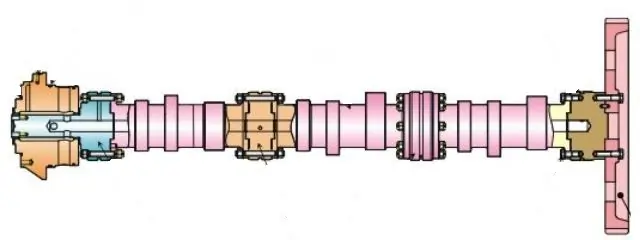
Camshaft Function in Diesel Engine
Camshafts play a pivotal role in marine diesel engines by regulating the opening and closing of the engine’s intake and exhaust valves. The accuracy of the camshaft’s function directly impacts the engine’s efficiency, performance, and lifespan. A malfunctioning camshaft can decrease power, raise fuel consumption, and risk engine damage.
In this article, we aim to underscore the significance of camshafts in marine diesel engines and explain their operation. We’ll discuss different camshaft types, including flat tappets and roller camshafts, and emphasize their strengths and weaknesses. We’ll also address frequent camshaft-related issues such as wear, misalignment, and damage, offering guidance on detecting and solving these problems. To enhance the longevity and performance of your camshaft, we’ll suggest maintenance practices focusing on correct lubrication and regular inspection.
Suppose you work as a marine diesel engine mechanic or own a vessel. In that case, this article offers invaluable knowledge about camshafts: their purpose, functioning, and maintenance strategies to maximize engine performance and life.
Understanding the Camshaft in Diesel Engines:
The camshaft, a metallic rod featuring evident cams, converts circular motion into an oscillating movement. In four-stroke engines, the camshaft turns at a rate that’s half of the crankshaft’s speed.
It bears the essential task of regulating the valves, directing fuel injection pumps, and managing the governor. This piece delves deep into the intricacies of the camshaft, exploring its parts and their importance.
We’ll tackle the following aspects:
- Camshaft in Engines Explained: Identifying what a camshaft is and its location within an engine.
- Functioning of the Camshaft: Decoding the operations of a camshaft inside a machine.
- Distinguishing Camshaft from Crankshaft: Spotlighting the differences between these pivotal engine elements.
- Camshaft’s Purpose: Clarifying its fundamental roles and functions.
- Camshaft Materials: Investigating the specific materials constituting a camshaft and the reasons behind their selection.
- Production of Camshafts: An introduction to the steps and methods in camshaft fabrication.
Join us as we dissect these camshaft elements, presenting clear insights tailored to specialists and experts.
Complete Description of Camshaft
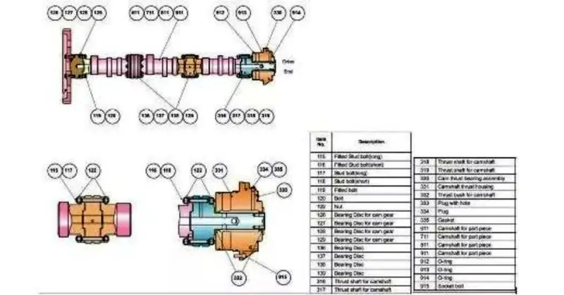
The above image is of a split type for individual cylinders, and screws join each piece. Each piece has a fuel injection cam, intake, and exhaust cam.
Joint screws inspection
Check the joint screws at every available opportunity. Then, carry out the screw for tightness.
Take out the loose stud and carry out a careful inspection. Replace the nut and studs in case of damage or transformation.
Apply the Loctite 243 and tighten the nuts and studs’ prescribed torque. Inspection of cams and bearings
Inspect each section’s operating surfaces, cams, and bearings regularly by turning the flywheel. Carefully inspect the bearings for any abnormal color or dropping of bearing material particles.
In case of suspicion, remove the thrust and inspect the bearing surfaces by sliding the camshaft on one side.
In case of any damage or abnormal condition, inform the engine manufacturer.
Camshafts and drives
The Design of the Engine decides the position of the camshaft in an engine. For example, the location of the camshaft could be in the engine block near the crankshaft. This arrangement is a push rod or overhead valve system.
No. of camshaft will be the engine type. There will be one camshaft in inline engines, whereas, in “V” shapes engines, two camshafts mount for each bank. In both designs, the job of the camshaft is the same, driving the Valve mechanism, Engine pumps, and distributor.
The camshaft material is generally a hardened alloy of iron or steel cast. And with proper machining. Cams lobes are properly grinding in shape and position to one other as per the engine firing order. Machining accuracy is vital. There will be fast wear and noisy operation due to bad shape and excessive worn out.
The bearing journals are a smooth grind finish surface. The gear for driving the distributor is the smooth ground finish on the camshaft. cam lobes get the induction hardening treatment.
There is a cam for each valve and fuel pump operation.Camshaft have gears for driving the pumps and distributor.
Cam lobes perform the following three jobs.
- Opening of Valve in proper time.
- Providing the proper lift
- Keeping the valve open for sufficient time and letting it close the valve at the exact time.
Proper valve timing is vital. Therefore, valve timing will be different for the different engines as per the specified manufacturer’s specifications of the valve timing diagram.
Cam profile is a term used for the cam shape. The valve lift starts from the base circle shown as a valve is fully closed, and there is the clearance between the rocker arm and the valve stem. To open the valve fully open, the nose of cam B is rotated by the cam.
Valve is gradually closed by the closing of flank C. For the engines, without a valve adjuster, a ramp is machined in the cam profile. The ramp is provided for easy operation during the valve opening. The shape of the lobe determines the valve opening period.
Camshaft timing should be perfect for synchronized running with the crankshaft. The timing is carried out with the gears or chains.
Camshaft Drive Arrangemets
Timing belt used in the Engine with the camshaft located at a distance.
Lube oil to chain drive system is supplied by the engine system. Noise and vibrations are reduced with the help of guides used by the chain.
Fibber glass or wire reinforced is used for the manufacturing of a toothed timing belt. Teeth of the belt match with the teeth on the crankshaft and camshaft pulley.
Timing belts usually require regular manual tensioning though the timing belts are quieter than the chains. Therefore, the life of timing belts is shorter. Due to this fact, frequent replacement is needed. In addition, any breakage of the belt during the engine operation may cause heavy damage.
Cam Lobe Terminology (The Best Guide On Camshafts For Diesel Engines)
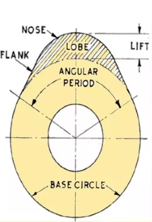
- Base Circle
- Angular Period
- Flank
- Lift
- Nose
Base Circle;-The Base circle is the part of the Cam aligned with the bearings and has zero lift.
Ramp;- Shortly adjoining to the base circle, the portion of the Cam with low momentum for preventing the extensive bump as the sluggishness is eliminated from the valve trains at the beginning of the lift action. Alike, a closing ramp is used for the gently seating of valve without any bounce off the seat.
Angular Period;- The time taken to travel the distance between the end of starting ramp and the start of the closing ramp is known as an angular period.
Flanks;- The flank is the part of the Cam responsible for the quickest movement of Valves with significant velocity and acceleration.
Lift; – Vertical distance between the base circle and the nose is known as cam lift.
Nose; – Nose is the part of the Cam with the greatest lift, opposite to the heel with the smallest radius.
Camshaft lobe separation angle and effect on the engine (The Best Guide On Camshaft For Diesel Engines)
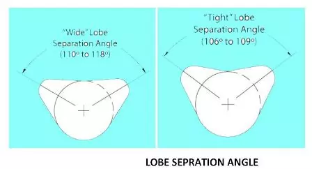
The lobe separation angle is the radial distance between the centreline of the inlet and exhaust lobe.
Wide lobe separation lets torque form above a broader speed range and produces enhanced power in the higher speed range. Conversely, the narrow lobe separation produces the peak torque to develop initially in the speed range and cultivates excellent speedup.
Overlap
In this phenomenon, the inlet valve opens just before the end of the exhaust stroke before releasing all the exhaust gases, providing more time for the intake air to enter and efficiently complete the scavenging process.
The valve lift and its effect on the Engine operation
Valve lift is the distance by which the valve is raised from its seating position to a fully open position. Consolidation of Rocker arm ration and lobe lift of camshaft will determine the valve lift. The valve lift and the valve speed is the main factor in deciding the intensity of engine torque.
Camshaft Intake and Exhaust centerline
The maximum lift of lobe with respect to the TDC and crankshaft revolution in degrees is the centre line of inlet and exhaust cam lobes. The centreline can be altered by advancing or retarding position. Advancing and retarding part of the cam will change the power output of an engine. The speed range will go down by advancing, and the speed range will increase by retarding the intake center line.
Camshaft materials (The Best Guide On Camshaft For Diesel Engines)
- Iron (Harden able)
This iron grade consists of CI (Cast iron) grade 17 with 1% chrome to create 5 to 7 % carbide. On completion of the casting process, the Material is subject to Induction hardening to give a Rockwell hardness of 52 to 56 on the scale C. This type of material is not suitable for use in overhead cams.
- Chilled Chrome Cast iron; – This material comprises grade 17 cast iron with 1% chrome. During the casting of the camshaft in the foundry, cam lobes are incorporated into the mold. While pouring the iron, the pored hardens off immediately. This process is chilling. Precipitating the material of the cam lobe to form a pattern of carbide on the cam lobe. This material is resistant to scuffing. Cams with this manufacturing process are suitable for engines with an Overhead cam.
- Steel camshafts;-
- Carbon Steel.’- carbon steel consists of EN8/EN 99.
- Induction hardened camshaft use this type of material. In concurrence with the-roller and cam followers. Because of the thorough hardening qualities.
- Steels alloyed;- This material comprises EN351 and EN 34. This material is best while using against a follower manufactured by chilled process.
- Steel nitride;- This material comprises EN 40B. Steel nitride is the best material for use in camshafts after the process of nitride and finish. The quality is at par with the chilled iron—many current FI engines use this material.
Camshaft Manufacturing Process
- Casting; -In this process uses chill cast iron to manufacture camshaft. This process is prone to defects like shrinkage, porosity, cracks, and insufficient pouring. Nonetheless, cast camshafts with induction hardened cam lobes for higher loads in roller contact can use.
- Forging;For many high-loaded diesel engines, a steel bar camshaft manufactured. with the forging process is useful. These camshafts manufacturing is on a computer-aided forging system. with unified heat treatment or machined from a steel bar.
- Machining;- The machining process gives final dimensions to the cams.
The manufacturing process in detail
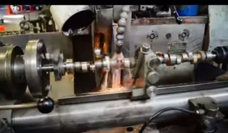
- Drilling and turning;- In this process, operator loads a raw forging in the machine. and turning and performs the drilling operation.
- Journal Grinding;- in this process. the operator grinds journals with the Carborundum wheels in the machine.
- Face grinding;- Face grinding is with the aid of an angular grinding wheel. At this stage, Operator Inspects by using the measuring gauges.
- Dowel hole drilling;- Grinding of the face is with reference to dowel holes.
- Lapping of the finished surfaces;- With the aid of lapping/emery papers. Operator super-finishes in microns on cams and oil seal area.
- Final cleaning with water and air;- Components cleaning for dust, oil, and chips is with the aid of a washing machine.
- Final Inspection; – Run out, and the measuring machine checks diameters of journals. The machine declares the component as OK, NG, or Bad.
Dismantling of Camshaft
To replace the camshaft section or bearing shell of the camshaft:
- Dismantle the area of the camshaft.
- Dismantle the cam section one by one through each cam side door.
- Loosen all the fuel injection pumps.
- Loosen all the rocker arms
- Dismantle all the pushrods and rocker arms.
- Remove the join nuts of the cams shaft
- Mark the assembly position location.
- Dismantle the thrust bearing of the camshaft.
- Dismantle the camshaft timing gear for the free axial movement of the camshaft during dismantling.
- Remove out the camshaft through the cam side door.
Remounting of Camshaft
Remounting procedure is the reverse of the dismantling procedure.
Check the following points.
- Carry out the mounting of the camshaft as per cylinder no marking on camshaft.
- Check the position marking on camshaft flanges and match the marking with the mating camshaft. Remount as per the TDC keeping on both camshafts. Fig
- Apply the coating of Loctite 243 on the threads.
- Apply the correct torque for tightening of nuts.
Function of the camshaft position sensor and does how it works?
In the latest design of Internal Combustion engines, the Electronic control unit (ECU) regulates the fuel injectors opening, creation of spark, Phase timing concerning the piston position in cylinders. ECU recognizes the position of each piston as per the signal of camshaft position.
The crankshaft and Camshaft position will be the base of determining the position of the piston in the cylinders. This information helps in performing the engine piston position recognition.
The Sensor transmits the signal to ECU to locate the exact position of the Camshaft.
The Sensor transmits the data to start the fuel injection sequence and precise control of the cylinders.
Where is the camshaft sensor located?
Camshaft position sensor mounts on the cylinder head cover. In fluctuating timing engines, the positioning of the gearwheel is on the camshaft position change system.
Blog Conclusion on Camshaft function in Diesel Engine
In conclusion, the camshaft is a critical component in diesel engines that plays a crucial role in controlling the opening and closing of the engine’s valves. The camshaft is responsible for transmitting power to the valves, which in turn allows air to enter and exit the engine, facilitating the combustion process.
The camshaft design is an important consideration for diesel engine manufacturers, as it affects engine performance and efficiency. The camshaft’s profile, including its lift, duration, and timing, can be optimized to achieve better fuel efficiency, power output, and emissions.
Moreover, advances in technology have allowed for the development of advanced camshaft systems that utilize hydraulic or electric actuators to vary the camshaft’s timing and lift, further enhancing engine performance and fuel economy.
Overall, the camshaft plays a critical role in the functioning of diesel engines, and its design and optimization are essential to achieving maximum engine efficiency and performance.
FAQ on Camshaft function in Diesel Engine
Q: What is a camshaft in a diesel engine? A: The camshaft is a cylindrical rod that controls the opening and closing of the engine’s valves in a diesel engine. It rotates at a specific speed and transmits power to the valves, allowing air to enter and exit the engine, which is critical to the combustion process.
Q: Why is the camshaft important in diesel engines? A: The camshaft is a critical component in diesel engines as it controls the opening and closing of the engine’s valves, which allows air to enter and exit the engine. This is critical to the combustion process, which is what powers the engine.
Q: What factors affect camshaft design in diesel engines? A: Several factors affect camshaft design in diesel engines, including engine displacement, desired power output, engine speed, fuel efficiency, emissions regulations, and the intended use of the engine.
Q: Can the camshaft profile be optimized for better engine performance? A: Yes, the camshaft profile can be optimized for better engine performance. The camshaft’s lift, duration, and timing can be adjusted to achieve better fuel efficiency, power output, and emissions.
Q: What are the advantages of advanced camshaft systems in diesel engines? A: Advanced camshaft systems in diesel engines can provide several advantages, such as variable valve timing, which can improve fuel efficiency and reduce emissions, as well as hydraulic or electric actuators, which can optimize engine performance in real-time based on driving conditions.
