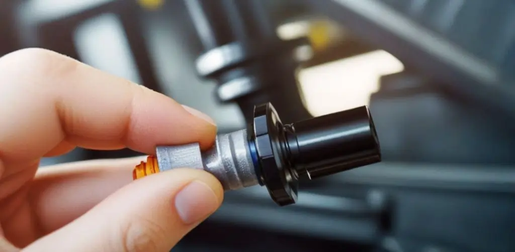
Crankshaft Position Sensor
A Crankshaft Position Sensor (CKP sensor) is a crucial component in modern internal combustion engines. It monitors the position or rotational speed of the crankshaft, providing real-time data essential for the engine control unit (ECU) to manage fuel injection and ignition timing. The precise functioning of CKP sensors is vital for optimal engine performance, fuel efficiency, and emissions control. In today’s advanced engines, the importance of these sensors cannot be overstated, as they ensure smooth and reliable operation, diagnose potential issues, and contribute to overall vehicle safety.
This blog post will explore the five most powerful benefits of CKP sensors, highlighting their role in enhancing engine performance, improving fuel efficiency, reducing harmful emissions, providing reliable diagnostic information, and increasing safety and reliability. By understanding these benefits, you’ll appreciate why CKP sensors are indispensable in modern automotive technology.
Working Principle of CKP Sensors
Overview of Technologies Used in CKP Sensors
Crankshaft Position Sensors (CKP sensors) are critical for the accurate monitoring of the crankshaft’s position and rotational speed in internal combustion engines. Three primary technologies are used in CKP sensors: Magnetic, Hall Effect, and Optical sensors. Each type has unique working principles, advantages, and applications in various engine systems.
1. Magnetic Sensors
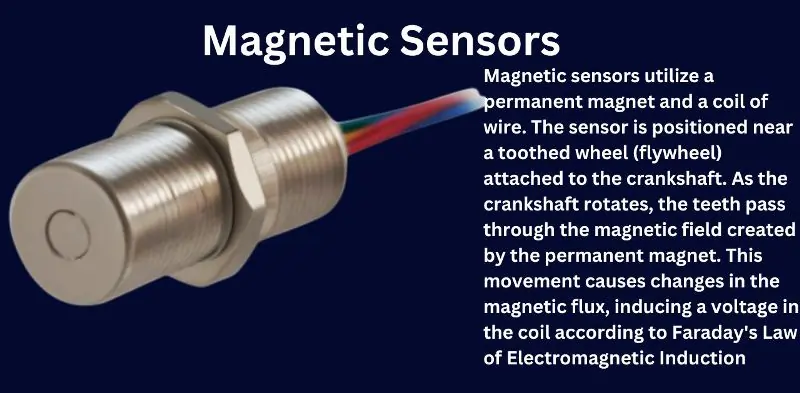
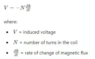
Working Principle: Magnetic sensors utilize a permanent magnet and a coil of wire. The sensor is positioned near a toothed wheel (flywheel) attached to the crankshaft. As the crankshaft rotates, the teeth pass through the magnetic field created by the permanent magnet. This movement causes changes in the magnetic flux, inducing a voltage in the coil according to Faraday’s Law of Electromagnetic Induction:
Advantages:
- Simple construction and cost-effective.
- High reliability and durability.
- Does not require an external power source.
Applications:
- Widely used in older vehicles and simpler engine systems.
- Suitable for environments with high temperatures and harsh conditions.
2. Hall Effect Sensors
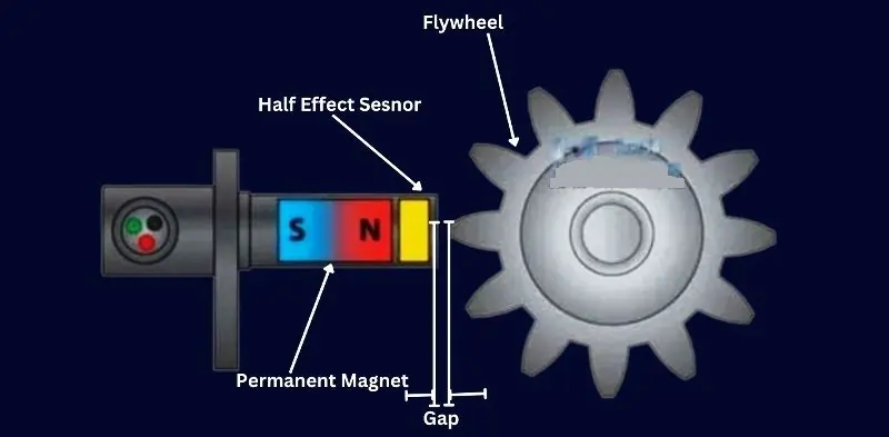
Working Principle: Hall Effect sensors operate using a Hall element, which is a semiconductor device. When the crankshaft rotates, the teeth on the flywheel pass near the Hall element. This disrupts the magnetic field generated by a nearby permanent magnet, causing a voltage change in the Hall element. The output voltage is directly proportional to the magnetic field strength, which varies with the position of the teeth.
Advantages:
- Provides a digital signal, making it easier to interface with modern electronic control units (ECUs).
- High precision and stability over a wide range of temperatures.
- Capable of detecting both position and speed of the crankshaft.
Applications:
- Commonly used in modern vehicles with advanced engine management systems.
- Ideal for applications requiring precise timing and control, such as fuel injection and ignition systems.
3. Optical Sensors
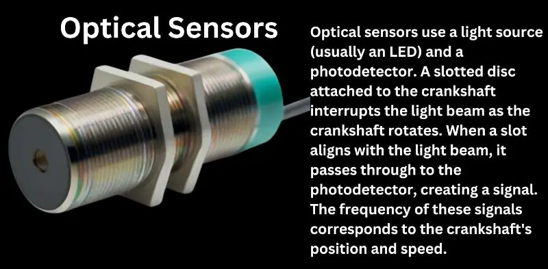
Working Principle: Optical sensors use a light source (usually an LED) and a photodetector. A slotted disc attached to the crankshaft interrupts the light beam as the crankshaft rotates. When a slot aligns with the light beam, it passes through to the photodetector, creating a signal. The frequency of these signals corresponds to the crankshaft’s position and speed.
Advantages:
- Extremely high accuracy and resolution.
- Can be used to measure very small angular movements.
- Not affected by magnetic interference.
Applications:
- Less common in automotive applications due to sensitivity to dirt and oil.
- Used in high-precision applications where cleanliness can be maintained, such as laboratory equipment and some high-performance engines.
Advantages and Applications of Each Technology
- Magnetic Sensors: Best for rugged environments and cost-sensitive applications. Ideal for older and simpler engine systems where high precision is not critical.
- Hall Effect Sensors: Preferred in modern vehicles due to their digital output and high precision. Suitable for applications requiring detailed timing and speed information, such as fuel injection and ignition control.
- Optical Sensors: Used in environments where high precision is necessary and conditions can be controlled to avoid contamination. Suitable for laboratory settings and specialized high-performance engines.
Working of a Crankshaft Position Sensor
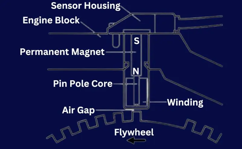
Sensor Housing
The sensor housing is the outer casing that protects the internal components of the Crankshaft Position Sensor from environmental factors like dust, moisture, and heat. It is typically made from durable materials that can withstand the harsh conditions within the engine compartment.
Engine Block
The CKP sensor is usually mounted on the engine block, near the crankshaft or flywheel. This positioning allows it to accurately monitor the rotational position of the crankshaft as it spins.
Permanent Magnet
At the heart of many CKP sensors is a permanent magnet. This magnet generates a steady magnetic field. The magnet’s north (N) and south (S) poles are crucial for the sensor’s operation, as they create the magnetic flux that interacts with the other components.
Pin Pole Core
The pin pole core is a ferromagnetic core located within the sensor housing. It concentrates and directs the magnetic field generated by the permanent magnet. This core ensures that the magnetic flux is focused on the area where the sensor will detect changes caused by the rotating crankshaft or flywheel.
Winding
Surrounding the pin pole core is a coil of wire known as the winding. As the magnetic flux changes due to the rotation of the crankshaft, it induces a voltage in this winding. This induced voltage is the electrical signal that the sensor sends to the engine control unit (ECU). The voltage induced (V) in the winding can be calculated using Faraday’s Law of Electromagnetic Induction:
Air Gap
The air gap is the small space between the sensor and the rotating crankshaft or flywheel. It is critical for the sensor’s operation because it ensures that the sensor can detect changes in the magnetic field without making physical contact with the rotating parts. The size of the air gap must be precise to ensure accurate readings.
Flywheel
The flywheel is an integral part of the engine’s crankshaft system. It has teeth or notches that pass by the sensor as the crankshaft rotates. These teeth disrupt the magnetic field created by the permanent magnet and pin pole core, causing fluctuations in the magnetic flux.
Operation
As the crankshaft rotates, the teeth on the flywheel pass through the air gap, causing disturbances in the magnetic field. When a tooth approaches the sensor, it alters the magnetic flux, inducing a voltage in the winding. This change in voltage corresponds to the position of the crankshaft. The sensor continuously sends these signals to the ECU, which interprets the data to determine the exact position and speed of the crankshaft.
By monitoring these fluctuations, the ECU can precisely control the timing of fuel injection and ignition, optimizing engine performance and efficiency. This seamless integration of components—sensor housing, engine block, permanent magnet, pin pole core, winding, air gap, and flywheel—ensures that the CKP sensor provides accurate and reliable data essential for modern engine management systems.
The 5 Most Powerful Benefits
Enhanced Engine Performance
| Aspect | Description |
|---|---|
| Real-Time Data on Crankshaft Position | The CKP sensor continuously monitors the crankshaft’s position and rotational speed, providing real-time data to the engine control unit (ECU). This data is crucial for synchronizing various engine functions. |
| Precise Fuel Injection and Ignition Timing | Accurate crankshaft position data allows the ECU to precisely control the timing of fuel injection and ignition. This ensures that fuel is injected at the optimal moment and the spark plug ignites the air-fuel mixture efficiently. |
| Impact on Engine Performance and Efficiency | The synchronization of fuel injection and ignition timing results in smoother engine operation, increased power output, and improved fuel efficiency. Proper timing also reduces engine knock and enhances overall performance. |
Improved Fuel Efficiency
| Aspect | Description |
|---|---|
| Optimizing Fuel Usage | The CKP sensor provides precise data on crankshaft position and speed, allowing the ECU to optimize the fuel injection process. This ensures that the correct amount of fuel is injected at the right time, reducing wastage and improving combustion efficiency. |
| Accurate Rotational Speed Measurement | By accurately measuring the crankshaft’s rotational speed, the CKP sensor enables the ECU to adjust the fuel injection timing to match engine load and speed. This synchronization enhances fuel efficiency by ensuring optimal fuel-air mixture combustion. |
| Examples of Fuel Efficiency Improvements | Vehicles with CKP sensors experience improved fuel efficiency due to better timing and reduced fuel wastage. For example, modern gasoline engines benefit from CKP sensors with precise fuel injection, leading to higher miles per gallon (MPG) and lower emissions. Diesel engines also see significant improvements in fuel economy and performance. |
Reduced Emissions
| Aspect | Description |
|---|---|
| Proper Timing of Fuel Injection and Ignition | The CKP sensor ensures precise timing of fuel injection and ignition by providing real-time data on the crankshaft position. This accuracy helps achieve optimal combustion, reducing incomplete combustion and the formation of harmful emissions. |
| Lower Emissions and Environmental Compliance | By optimizing the combustion process, the CKP sensor contributes to lower emissions of pollutants such as carbon monoxide (CO), hydrocarbons (HC), and nitrogen oxides (NOx). This aids in meeting stringent environmental regulations and standards. |
| Case Studies/Examples of Emission Reductions | Real-world applications have shown significant emission reductions. For example, modern vehicles with CKP sensors have reported a decrease in CO and HC emissions by up to 50%. Diesel engines equipped with CKP sensors have shown reduced NOx emissions, aiding compliance with Euro 6 standards. |
Reliable Diagnostic Information
| Aspect | Description |
|---|---|
| Diagnostic Data for Engine Problems | The CKP sensor provides crucial diagnostic data by continuously monitoring the crankshaft’s position and speed. Any irregularities detected by the sensor are communicated to the engine control unit (ECU), which helps in identifying potential engine issues early on. |
| Malfunctioning Sensors and Trouble Codes | When a CKP sensor malfunctions, it can trigger the check engine light on the vehicle’s dashboard. The ECU stores trouble codes that correspond to the specific issue with the sensor. These codes can be read with a diagnostic scanner, allowing technicians to pinpoint the problem quickly. |
| Benefits of Timely Diagnostics | Timely diagnostics enabled by the CKP sensor help maintain engine health and prevent major issues. Early detection of problems allows for prompt repairs, reducing the risk of severe engine damage. Regular monitoring ensures optimal performance and prolongs the engine’s lifespan. |
Increased Safety and Reliability
| Aspect | Description |
|---|---|
| Preventing Engine Misfires and Stalling | The CKP sensor plays a critical role in preventing engine misfires, stalling, and other operational issues by providing precise data on the crankshaft’s position and rotational speed. This ensures accurate timing of fuel injection and ignition, which is essential for smooth engine performance. |
| Contribution to Smooth Operation | By enabling accurate timing and synchronization of engine functions, the CKP sensor ensures that the engine runs smoothly and efficiently. This reduces the likelihood of sudden failures and enhances the overall reliability of the vehicle, leading to a more dependable driving experience. |
| Enhancing Overall Vehicle Safety | CKP sensors significantly enhance vehicle safety by preventing issues that could lead to breakdowns or accidents. For example, avoiding engine stalling at critical moments improves safety during driving. In modern vehicles, CKP sensors also contribute to advanced safety features like traction control and stability systems. |
FAQ on Crankshaft Position Sensor
Q1: What does a Crankshaft Position Sensor do?
A1: It monitors the crankshaft’s position and speed.
Q2: How can I tell if my CKP sensor is failing?
A2: Look for engine misfires, stalling, and a check engine light.
Q3: Can a faulty CKP sensor cause my car not to start?
A3: Yes, it can disrupt fuel injection and ignition timing.
Q4: How is a CKP sensor typically tested?
A4: Using an OBD-II scanner and a multimeter.
Conclusion
In summary, Crankshaft Position Sensors (CKP sensors) offer five powerful benefits: enhanced engine performance, improved fuel efficiency, reduced emissions, reliable diagnostic information, and increased safety and reliability. These benefits highlight the critical role CKP sensors play in modern internal combustion engines, ensuring precise timing of fuel injection and ignition, optimizing engine operations, and reducing environmental impact.
As automotive technology continues to advance, the importance of CKP sensors will only grow. Their role in maintaining engine efficiency, lowering emissions, and providing crucial diagnostic data makes them indispensable components in vehicles today and in the future. The ongoing development of sensor technology promises even greater precision and reliability, contributing to the evolution of more efficient, cleaner, and smarter engines.
In conclusion, CKP sensors are not just essential for current engine systems but are also pivotal in shaping the future of automotive innovation. Their continued evolution will significantly impact the automotive industry, leading to advancements that benefit both the environment and the driving experience.
