Cylinder Head of Diesel Engine
Marine diesel engine cylinder heads ensure combustion chamber sealing, precise air-fuel mixing, and optimal engine performance. This guide covers maintenance steps, troubleshooting, and tips for long-lasting reliability—all updated for 2025.”.
The Engine’s Heart
Think of the cylinder head as an engine’s heart. The cylinder head performs very important functions like sealing the combustion chamber, ensuring the proper mixture of fuel and air, maintaining the inflow of scavenged air, and expelling exhaust gases after the completion of the power stroke.
Without a good cylinder head, your diesel engine won’t work well, or maybe not.
Inside the Cylinder Head
Cylinder heads contain important parts like Valves, Fuel valves, Valve operating mechanisms, and indicator cocks. Each piece does a vital job of making the engine work. Understanding how these parts cooperate is essential.
Common Issues and Fixes
Like all engine parts, cylinder heads can wear out over long running hours. Cylinder heads might develop valve seat leakages, valve guides worn out, and leakages from the sealing surfaces. In this article, we will discuss the common challenges and to face them with easy tips. Sometimes, removing the cylinder head, replacing worn-out components, and ensuring everything is sealed tightly are required to remedy these issues.
Upon reading this post, you will learn the importance of a Cylinder head and will learn to solve cylinder head problems and serious issues during engine operation. Hence, stay with us to learn more in-depth about cylinder heads.
Diesel Engine Cylinder Head Fittings
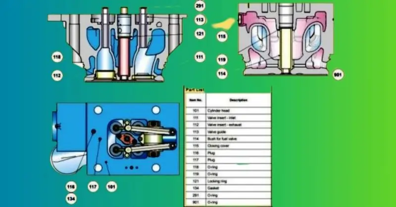
Components Housed in the Cylinder Head Bore
The cylinder head bore accommodates various crucial components:
Fuel Injector: This component injects fuel into the combustion chamber.
Inlet and Exhaust Valves: The inlet and exhaust valves are made of satellite-coated seats and nickel-based alloy valves with nemonic spindles. They play a vital role in controlling the flow of air and exhaust gases.
Valve Rotators: These mechanisms provide a slight rotation to the valves, increasing the life of the valve spindle.
Valve Seats and Valve Guides: Identical for both inlet and exhaust valves, these components are interchangeable. They are crucial for the proper functioning of the valves.
Seat Rings: Made of heat-resistant steel with direct hardening on the seat surface, seat rings help maintain low valve temperatures. Water cooling is employed to ensure optimal cooling.
Safety Valve: Installed in the cylinder head, the safety valve is essential for releasing excessive pressure, especially during high maximum pressure or hydraulic lock situations.
Fuel Injection Valve: Located in the interchangeable sleeve at the center of the cylinder head, this valve benefits from comprehensive water cooling in the nozzle tip space, eliminating the need for direct injection nozzle cooling.
Air Starting Valve: Used to initiate engine startup.
Rocker Arms: These components actuate the inlet and exhaust valves.
Coaming: The cylinder head includes a coaming that encloses the valve gears. The top cover can be securely tightened over the coaming, ensuring oil sealing of the entire chamber and full-face coverage of the cylinder head. An inspection cover in the coaming facilitates valve rotator inspection.
Intake Swirl: The valve pattern allows for a specific intake swirl through a 20-degree turning.
Cylinder Head Gasket: Four nuts and studs are used to secure the cylinder head over the cylinder liner with a cylinder head gasket, preventing leaks against the high combustion pressure in the combustion chamber. Hydraulic jacks are employed for tightening the nuts.
Cylinder head maintenance should be performed regularly for the best performance and reliability. Check holes in the cylinder head help detect any leakage between the cylinder head and cylinder liner mating surfaces.
Valve Rotator
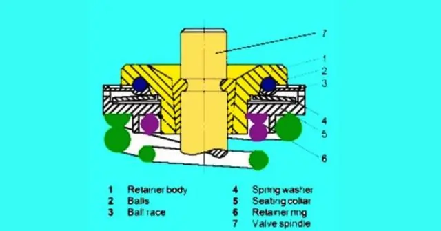
- The valve rotator retainer body (1) features multiple pockets in a circular arrangement.
- The ball race (3) serves as a track for balls moving in the opposite direction.
- The inner edge of the retainer body holds the spring washer (4), creating a counteractive springing effect.
- The sealing collar (5) envelops the spring washer, ensuring a secure fit.
- A retaining ring (6) is used to secure the assembled valve rotator and for removal purposes.
Advantages of Valve Rotators
Valve rotators are essential components in marine diesel engines, providing several key advantages:
Reduces Carbon Accumulation: Valve rotators help minimize carbon buildup on the valve guide and seat. Reduced carbon deposits at the valve lid will ensure the long lifespan and smooth operation of valves in the valve guide.
Maintains Uniform Valve Temperature: Valve rotators maintain a consistent valve temperature.
Keeping valves at the same temperature across the board helps your engine run better and prevents issues that can occur from valve heating or cooling unevenly.
Disassembling the Cylinder Head
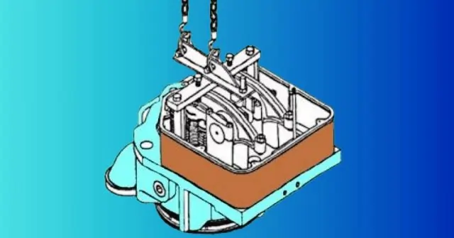
Here is the procedure for dismantling the cylinder head of a marine diesel engine:
- Begin by draining the cooling water from the engine.
- Next, remove the top cover of the rocker arm.
- Proceed to remove both side crankcase covers.
- Remove the cover of the exhaust.
- Take out the cylinder head clamps and the receiver for the exhaust gas.
- Remove the high-pressure (HP) pipe for fuel oil.
- Remove the clamps used to secure the freshwater connection between the cylinder heads.
- Remove the cooling oil inlet and outlet pipes.
- Take out the rocker arm lubricating oil pipes.
- Remove the thermometer attachment branch.
- Remove the exhaust pipe flanges.
- Loosen the cylinder head hydraulic tightening nuts using a hydraulic tool.
- Install the cylinder head lifting tool.
- Finally, lift the cylinder head with the assistance of the lifting tool.
Please ensure that you follow these steps carefully and take all necessary safety precautions during the dismantling process.
Exhaust and Inlet valve dismantling
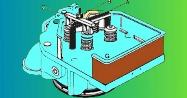
Exhaust and Inlet Valve Disassembly Procedure:
- Secure the cylinder head on a sturdy worktable.
- Install the valve spindle support device onto the head.
- Carefully detach the spring-loaded valve bridge.
- Utilize the specified tool as shown in the diagram.
- Gradually tighten nut (B) to compress the spring.
- Remove the valve cones, collets, and valve locks.
- Remove the valve rotators after removing nut (B) and Traverse (C).
- Remove the valve support device from beneath the worktable and extract the valves.
Valve seats and valve spindle inspection
Valve Seat and Valve Spindle Inspection:
- Conduct the lapping procedure if there is minor pitting or valve seat burn-out.
- For cases of excessive pitting, utilize a grinding machine to perform the valve seat grinding process.
Valve Guide Inspection
Valve Guide Inspection and Measurement:
- Inspect the valve guide for pitting marks or signs of exhaust gas leakage.
- Measure the valve guide bore dimensions.
Replace the valve guide if the bore dimensions exceed the specified limits.
Valve Seat ring and valve spindle re-conditioning
Valve seat re-conditioning procedure
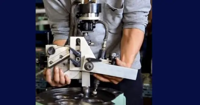
- Set the feed angle for grinding the seating surface according to the specified feed angle.
- Continue grinding until a clean and uniform surface is achieved.
- For the best surface finish, grind with an inward-to-outward feed direction.
- Continue grinding until recess R becomes visible. If no recess is observed, reject the seat.
Valve Seat Surface checking after reconditioning.
- After grinding the valve seat ring, check the contact between the valve seat ring’s seating surface and the valve spindle seat.
- Apply a thin layer of blue compound to the valve spindle seating surface.
- Insert the valve into the cylinder head’s valve guide.
- Rotate the valve back and forth by 1/3 turn with gentle pressure.
- Remove the valve and examine the contact pattern on the valve seat ring.
Observation: The contact pattern or mark should begin from the outer diameter and move radially inward. The contact area should be continuous and measure 2-3 mm width around the circumference.
Valve Spindle re-conditioning
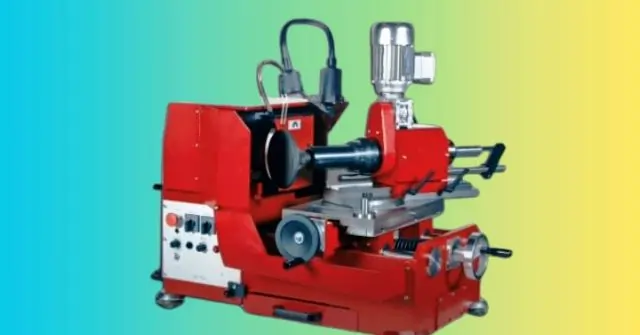
- Perform the reconditioning of valve spindles using a lathe machine.
- Attach the special grinding machine to the tool post of the lathe machine.
- Grind the seating surface of the valve spindle using the feed angle shown in the provided diagram.
- Continue grinding until the valve seat lid has a clean and even surface.
- The final check involves measuring the height ‘H.’
- Ensure that the achieved height ‘H’ matches the description in the diagram below.
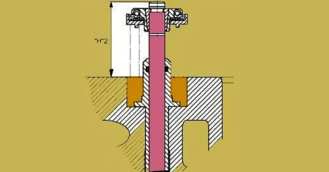
Check for the valve assembly.
Measure the height between the valve spindle’s top end and the cylinder head’s upper edge.
Valve Guide Replacement
It is mandatory to replace the valve guide if the clearance has increased more than the specified limits by the equipment manufacturer.
Valve Guide Removal and Replacement Procedure
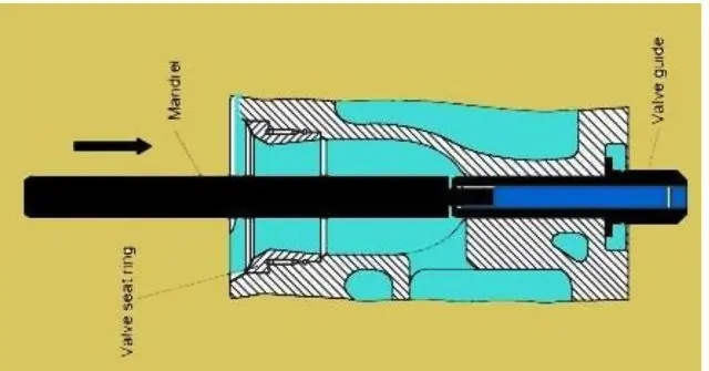
- Use a special mandrel with shoulders to blow out the valve guide from the bottom of the cylinder head. Ensure that the mandrel’s shoulders fit at the collar of the valve guide.
- Thoroughly clean the valve guide with compressed air.
- Inspect the bore’s surface for any abnormal marks that might hinder the proper fitment of the new valve guide.
- Cool the new valve guide to -70 degrees Celsius using dry ice or dry nitrogen.
- After inserting the new valve guide, gently tap the collar with a mandrel and hammer to ensure even seating in the cylinder head.
- Replace the old O-ring with a new one.
Safety Valve Maintenance
- Clean the safety valve thoroughly during engine standstill and major maintenance.
- Avoid increasing the spring tension to stop leaks, as this is not recommended.
- The opening pressure setting is indicated on the cap nut.
Safety valve dismantling procedure
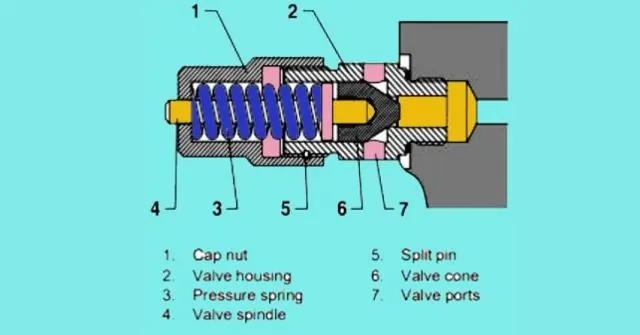
- Remove the safety valve from the cylinder head.
- Secure the valve in a table vice.
- Unscrew the cap nut (1).
- Remove the spring (3).
- Take out the valve (4).
- Remove the valve cone (6).
- After thorough cleaning, inspect the valve for any damage. If required, perform valve reconditioning.
Safety valve assembly procedure
- Apply copaslip or an appropriate substitute to the valve housing threads.
- Reassemble the safety valve following the reverse sequence of steps 1 to 7.
Safety Valve Testing
- After each overhaul, conduct a leak test and opening pressure test. Connect the safety valve to the Fuel injection test pump using a high-pressure fuel injection pipe.
- Continuously vent the system by pumping until air-free bubbles emerge from the port (7) in the valve body (2).
- Conduct the Safety Valve Leakage Test. Gradually raise the pressure to 135 bars.
- Monitor the pressure for 01 minutes. It should not drop below 135 bars during this time.
- If the pressure remains constant for 01 minutes, proceed to raise the pressure to the opening pressure.
- If the pressure falls below 135 bars within 01 minutes, consider lapping or reconditioning the valve.
- Increase the pressure to the specified opening pressure.
- Complete the testing procedure if the valve opens correctly at the opening pressure.
- Adjust the cap nut (1) to achieve the correct lifting pressure if the valve does not open at the specified pressure.
- Drill a hole to secure the safety pin (5).
Reinstallation of the Safety Valve:
- Apply copaslip to the threads on the valve housing.
- Reassemble the safety valve into the cylinder head.
Maintenance Procedures for Indicating Valve, Injector Sleeve, Valve Seat Ring, and Cylinder Head in Marine Diesel Engine
Indicating Valve Maintenance
- Under normal working conditions, minimal maintenance is required for the indicating valve, except during cylinder head maintenance/overhaul.
- Dismantle the indicating valve.
- Visually inspect the valve cone and seat for any signs of burning through.
- Replace the entire valve if the valve seat in the housing is persistently turning.
- Clean and lubricate all valve parts thoroughly before reassembly.
- Ensure the valve spindle is fully open during reassembly to prevent seat damage.
Injector Sleeve Replacement
Fuel Injector Sleeve Removal:
- Remove the snap ring using two screwdrivers.
- Drive out the sleeve from the bore with a hammer and brass mandrel.
Inspect the cylinder head bore for sleeve installation.
- Clean and inspect the bore for any burrs or surface irregularities hindering sleeve installation.
- Smooth the surface lightly with soft emery paper.
- Lubricate the sealing ring surface with oil/grease.
- Cool the sleeve to -15°C using dry ice.
- Insert a new sealing ring on the sleeve.
- Apply Loctite 572 to the sealing surface of the sleeve.
- Install the sleeve in the bore and secure it with a snap/lock ring.
Valve Seat Ring Replacement
Extraction of Valve Seat Ring
- When reconditioning is not feasible due to excessive dimensions, reject the valve seat ring.
- Use a special extractor tool consisting of various components.
- Vertically place the guide disc through the valve seat ring, guided by the guide pin.
- Fit the guide disc to contact the lower part of the cylinder head.
- Install a hydraulic jack with the guide disc and hexagon collar nut.
- Pump up the hydraulic pressure to extract the valve seat ring.
Fitting a New Valve Seat Ring
- Clean and inspect the bore for any marks hindering the seat’s fitment.
- Use specific tools as per the provided illustration.
- Cool the valve seat ring to at least -25°C for easy insertion.
- Insert the O-ring with a coating of oil/Loctite.
- Position the valve seat ring in the bore, secure and center it with a valve seat grinding machine.
Cylinder Head Mounting
- Inspect the cylinder head and cylinder liner top for cleanliness and damage.
- Replace the O-ring in the cooling water passage.
- Lubricate the O-ring with oil.
- Inspect the nuts and threads for cleanliness and damage.
- Place the cylinder head on top of the cylinder liner.
- Check the nuts for proper thread engagement.
- Apply molycote on the mating and threaded parts.
- Tighten the nuts with a Tommy bar.
- Tighten and loosen a new nut to relieve deformation.
- Adjust the tappet clearance.
- Reinstall all pipelines, supporting frames, and covers.
- Perform leakage tests for lube oil and cooling water.
Cylinder Head Cooling Water Spaces Inspection
- Inspect the cooling water inlet and outlet as per the provided figure.
- Describe the entire cylinder head if scale formation is present.
- Check for blockages by pouring water into the inlet and observing flow from the outlet.
- Use a wire brush for cleaning and proper flushing.
Balancing Yoke Adjustment
- The yoke presses the inlet and exhaust valves simultaneously.
- Properly balance the yoke for even and smooth valve operation.
- Incorrect clearance adjustments on the yoke can lead to unbalanced forces, causing damage.
- Follow the adjustment procedure to balance the yoke effectively.
- Tighten the locknut to prevent turning during adjustment and apply the correct torque.
Tappet /Valve clearance adjustment
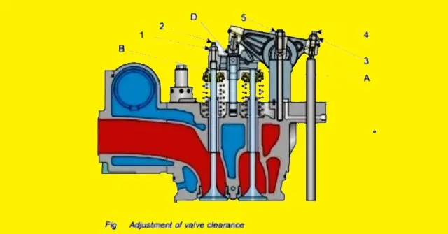
- Replace the wearing parts on the rocker arm assembly after the proper checking.
- Check the tightness of the rocker arm holding nut (5). Re-tighten the nut if found loose.
- Apply the molycote and Check the tightness with the specified torque.
- Locking nut (3) and adjusting screws (4) on the rocker’s arm will be loosened.
- Check the clearance by dial gauge and feeler gauge.
- Turn the adjusting screw (4) until the bottom of the adjusting screw contacts a pushrod. Simultaneously, watch the dial gauge movement.
- Tighten the locknut (3) while holding the adjusting screw arresting the turning movement and tightening the lock nut.
- Re-measure the clearance for confirmation while pressing the pushrod side upon completion of the locknut tightening.
Blog Post Conclusion
In conclusion- It is responsible for sealing the combustion chamber, allowing proper compression and ignition of the fuel and air mixture, and housing the valves that control air and exhaust flow.
During maintenance or overhaul, various components within the cylinder head require attention. This includes the indicating valve, injector sleeve, valve seat ring, and overall cylinder head inspection.
These components must be examined, replaced, and reconditioned according to the right processes.
Balancing the yoke and adjusting clearances play a significant role in the smooth operation of valves within the cylinder head.
You may love to read our amazing post on : Connecting Rod: The Best Tutorial of 24-25
FAQ on ” Cylinder Head of Diesel Engine
Q2: Why is maintaining the cylinder head important?
A2: Proper maintenance ensures engine efficiency and reliability.
Q4: What’s the significance of balancing the yoke in the cylinder head?
A4: Balancing ensures even valve operation and prevents engine damage.
Q3: How do you check the condition of a cylinder head?
A3: Inspect for wear, damage, and cleanliness during maintenance.
Q1: What is the role of the cylinder head in a diesel engine?
A1: The cylinder head seals the combustion chamber and houses important engine components.
