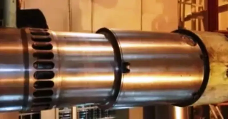
Cylinder Liners
Cylinder liners are vital components in modern engines, essential for ensuring the durability and efficiency of engines used in cars, ships, and industrial machines. This tutorial provides engineers with a clear and comprehensive guide to understanding cylinder liners.
We will start by explaining what cylinder liners are and their key functions. Then, we’ll explore different types of cylinder liners and the materials used to make them. You’ll learn about the manufacturing processes, how to install and maintain them, and ways to enhance their performance. We’ll also share real-world examples of cylinder liners in action and look at the latest trends and innovations in this field. Whether you’re a seasoned engineer or just starting out, this guide will give you the knowledge you need to work with cylinder liners effectively.
Understanding Cylinder Liners
What are Cylinder Liners?
Cylinder liners, also known as engine sleeves, are cylindrical components inserted into the engine block to form the inner wall of the cylinder. They provide a smooth and durable surface for the piston to move within, ensuring efficient engine operation. Cylinder liners are crucial for the overall performance and longevity of an engine, as they bear the brunt of the friction and heat generated during combustion.
The Role of Cylinder Liners in an Engine
The primary function of cylinder liners is to protect the engine block from wear and damage. They create a surface that can withstand high temperatures and pressures while reducing friction between the piston and the cylinder wall. Cylinder liners also facilitate better heat dissipation, preventing the engine from overheating. Additionally, they help maintain the compression within the cylinder, ensuring optimal combustion and engine efficiency.
Different Types of Cylinder Liners
Cylinder liners come in various types, each designed to suit specific engine requirements and applications. The three main types of cylinder liners are:
Dry Liners
- Definition: Dry liners are thin, removable sleeves that fit snugly into the cylinder block without direct exposure to the engine coolant.
- Features: These liners rely on the contact with the engine block for heat dissipation.
- Advantages: Easier to replace and maintain, cost-effective, and suitable for smaller engines.
- Applications: Commonly used in light-duty engines and smaller vehicles.
Wet Liners
- Definition: Wet liners are thicker sleeves that come into direct contact with the engine coolant, allowing for better heat dissipation.
- Features: These liners have seals at the top and bottom to prevent coolant leakage into the combustion chamber.
- Advantages: Superior cooling, better thermal management, and reduced engine overheating.
- Applications: Ideal for heavy-duty engines, trucks, and marine applications.
Cast-In-Place Liners
- Definition: Cast-in-place liners are integral parts of the engine block, formed during the casting process.
- Features: These liners are permanent and cannot be replaced without extensive machining.
- Advantages: Higher structural integrity, reduced risk of liner movement, and better heat transfer.
- Applications: Commonly found in high-performance engines and industrial machinery.
Material Selection for Cylinder Liners
Common Materials Used
Cylinder liners are manufactured from various materials, each selected for its specific properties to meet the demands of different engine applications. The most common materials used for cylinder liners include:
- Cast Iron (Fe-C): Known for its excellent wear resistance and ability to withstand high temperatures. Cast iron liners are durable and provide a good balance between cost and performance.
- Steel (Fe-C): Offers superior strength and durability. Steel liners can handle higher pressures and temperatures, making them ideal for heavy-duty and high-performance engines.
- Alloyed Materials: These liners are made from a combination of metals, such as:
- Nickel (Ni): Enhances corrosion resistance and toughness.
- Chromium (Cr): Improves hardness and wear resistance.
- Molybdenum (Mo): Increases strength and thermal stability.
Material Properties
When selecting materials for cylinder liners, several key properties must be considered to ensure optimal performance and longevity. These properties include:
- Durability: The material must be able to withstand prolonged use without significant wear or damage. This is critical to maintaining the engine’s efficiency and performance over time.
- Heat Resistance: Cylinder liners are exposed to extreme temperatures during engine operation. The chosen material must have high thermal stability to prevent deformation and maintain its structural integrity under heat stress.
- Friction Reduction: To minimize wear and tear on both the liner and the piston, the material should have low friction properties. This reduces the energy loss due to friction and contributes to smoother engine operation.
Choosing the Right Material: Factors to Consider
Selecting the appropriate material for cylinder liners involves evaluating several factors to match the specific requirements of the engine and its operating conditions. Key factors to consider include:
- Engine Type and Application: Different engines have varying demands based on their usage. For instance, high-performance racing engines require materials with superior strength and heat resistance, while standard automotive engines might prioritize cost-effectiveness and durability.
- Operating Conditions: The environment in which the engine operates, including temperature ranges, pressure levels, and exposure to corrosive elements, influences material selection. Materials that can handle extreme conditions or frequent temperature fluctuations are preferred for certain applications.
- Cost and Availability: Budget constraints and material availability can also impact the selection process. While high-end materials like certain alloys may offer better performance, they can be more expensive and harder to source.
- Compatibility with Other Engine Components: The chosen material must be compatible with other engine components to avoid issues like galvanic corrosion. Ensuring material compatibility can extend the overall lifespan of the engine.
Manufacturing Processes for Cylinder Liners
Casting: Detailed Overview of the Casting Process
Casting is one of the most common methods used to manufacture cylinder liners. This process involves pouring molten metal into a mold where it solidifies into the desired shape. The steps in the casting process include:
- Pattern Making: A pattern of the cylinder liner is created, usually from wood or metal, which is used to form the mold cavity.
- Mold Preparation: The mold is prepared using sand or other materials around the pattern, leaving a cavity in the shape of the liner once the pattern is removed.
- Melting: The selected metal (e.g., cast iron or alloy) is melted in a furnace at high temperatures.
- Pouring: The molten metal is poured into the mold cavity, filling the space and taking the shape of the liner.
- Cooling: The metal is allowed to cool and solidify within the mold.
- Removal and Finishing: The solidified liner is removed from the mold, and any excess material or rough edges are trimmed and finished.
This method is cost-effective and suitable for producing large quantities of liners with complex shapes. However, it requires precise control of temperature and cooling rates to ensure high-quality products.
Tolerances and Allowances in Casting:
- Tolerance: The permissible limit of variation in a physical dimension. For cylinder liners, the tolerance is often specified to ensure the liner fits perfectly within the engine block.
- Example Formula: Tolerance=±(0.001×Nominal Dimension)
- Allowance: The intentional dimensional difference provided to facilitate proper fit. Allowance ensures that after machining and finishing, the parts fit together correctly.
- Example Formula: Allowance=Nominal Dimension−Machining Allowance
Centrifugal Casting: Benefits and Applications
Centrifugal casting is a specialized casting method where molten metal is poured into a rotating mold. The centrifugal force distributes the metal evenly around the mold, resulting in a dense and homogeneous structure. The steps in the centrifugal casting process include:
- Mold Rotation: The mold is rotated at high speeds around its axis.
- Pouring: Molten metal is introduced into the rotating mold. The centrifugal force causes the metal to spread and solidify uniformly along the mold walls.
- Cooling: The metal cools and solidifies quickly due to the rapid rotation and even distribution.
- Extraction: The solidified liner is removed from the mold, and any necessary finishing touches are applied.
Benefits:
- Produces liners with fine-grained structures and high mechanical strength.
- Reduces porosity and inclusions, leading to improved durability.
- Ideal for producing cylindrical parts with high precision and consistency.
Applications:
- Used in high-performance and heavy-duty engines where superior material properties are required.
- Common in automotive, aerospace, and industrial applications where reliability and strength are paramount.
Tolerances and Allowances in Centrifugal Casting:
- Tolerance: Centrifugal casting generally allows for tighter tolerances due to the uniform distribution of metal.
- Example Formula: Tolerance=±(0.0005×Nominal Dimension)
- Allowance: Similar to standard casting but can be adjusted for the specific benefits of centrifugal force.
- Example Formula: Allowance=Nominal Dimension−Centrifugal Machining Allowance
Shrink Fit and Press Fit Methods: Pros and Cons
Shrink fit and press fit methods are used to install cylinder liners into the engine block, ensuring a tight and secure fit.
Shrink Fit Method:
- Process: The cylinder liner is heated to expand its diameter and then inserted into the engine block. As the liner cools, it contracts and forms a tight fit within the block.
- Pros: Provides a strong and secure fit, minimizes the risk of liner movement during engine operation, and ensures good thermal contact for heat dissipation.
- Cons: Requires precise temperature control and handling to avoid damage to the liner or engine block.
Tolerances and Allowances in Shrink Fit:
- Interference Fit Tolerance: Ensures the liner contracts to a tight fit after cooling.
Example Formula: Tolerance=±(0.0008×Nominal Dimension) - Allowance for Expansion: The amount by which the liner diameter must be larger before heating.
Example Formula: Allowance=Nominal Diameter+(α×ΔT×Nominal Diameter)
Where α is the coefficient of thermal expansion and ΔT is the temperature change.
Press Fit Method:
- Process: The cylinder liner is mechanically pressed into the engine block at room temperature using hydraulic or mechanical presses.
- Pros: Simpler and faster installation process, does not require heating equipment, and is cost-effective for mass production.
- Cons: May not provide as secure a fit as the shrink fit method, and there is a higher risk of liner movement under extreme operating conditions.
Tolerances and Allowances in Press Fit:
- Press Fit Tolerance: Ensures the liner is pressed in securely without excessive force.
Example Formula: Tolerance=±(0.0005×Nominal Dimension) - Allowance for Press Fit: The interference amount required for a secure press fit.
Example Formula: Allowance=Nominal Diameter+(0.001×Nominal Diameter)
Installation and Maintenance of Cylinder Liners
Installation Procedures: Step-by-Step Guide
Proper installation of cylinder liners is crucial for the optimal performance and longevity of the engine. Below is a step-by-step guide to installing cylinder liners:
- Preparation:
- Ensure the engine block and cylinder liners are clean and free of debris.
- Inspect the engine block for any signs of damage or wear.
- Measure the bore of the engine block and the outer diameter of the liner to ensure proper fit.
- Dry Fit:
- Place the liner into the engine block without any heating or pressing to check the fit.
- Ensure the liner sits evenly and snugly in the block.
- O-Ring Replacement and Lubrication:
- For wet-type cylinder liners, replace the cylinder liner O-rings at the upper and lower parts of the liner.
- Inspect the O-ring grooves for any debris or damage.
- Apply a thin layer of appropriate lubricant to the O-rings to ensure a proper seal and ease of installation.
- Install the O-rings carefully into their respective grooves on the liner, ensuring they are seated correctly without twists or kinks.
- Shrink Fit Method:
- Heat the liner to expand it. This can be done using an oven or induction heater.
- While the liner is being heated, place the engine block in a freezer or cool it using dry ice to slightly contract the bore.
- Quickly insert the heated liner into the cooled block, ensuring it aligns correctly.
- Allow the liner and block to return to room temperature naturally.
- Press Fit Method:
- Apply a thin layer of lubricant to the liner and engine block bore to reduce friction.
- Use a hydraulic or mechanical press to insert the liner into the block. Apply steady and even pressure.
- Ensure the liner is pressed in to the correct depth and sits flush with the engine block surface.
- Final Checks:
- Verify that the liner is properly seated and there are no gaps or misalignments.
- Check the inner diameter of the liner to ensure it meets the engine’s specifications.
Common Issues: Troubleshooting Installation Problems
During the installation of cylinder liners, several issues can arise. Here are common problems and their solutions:
| Problem | Description | Solution |
|---|---|---|
| Misalignment | The liner is not seated correctly, causing misalignment. | Remove the liner and recheck the alignment of the engine block and liner. Ensure surfaces are clean. |
| Excessive Force Required | Difficulty in pressing the liner into the block. | Check for proper lubrication and ensure correct bore and liner dimensions. Heat the liner if needed. |
| Cracks or Damage | The liner or engine block cracks during installation. | Inspect for pre-existing damage. Ensure even pressure during press fit and avoid overheating. |
| Coolant Leakage | Coolant leaks around the liner after installation. | Check seals and gaskets. Ensure they are correctly installed and replace if damaged. |
Maintenance Tips: Best Practices for Longevity
Regular maintenance of cylinder liners can significantly extend their lifespan and ensure optimal engine performance. Here are some best practices for maintaining cylinder liners:
| Maintenance Task | Description |
|---|---|
| Regular Inspections | Periodically inspect liners for signs of wear, scoring, or corrosion. Measure the inner diameter for excessive wear. |
| Proper Lubrication | Use high-quality engine oil. Change oil and filter regularly as per manufacturer’s recommendations. |
| Coolant System Maintenance | Maintain the coolant system to prevent overheating and corrosion. Regularly check and replace coolant and inspect O-rings. |
| Cleaning | Keep the engine clean to prevent contaminants from entering the liners. Use appropriate cleaning agents for carbon deposits. |
| Avoid Overloading | Operate the engine within designed load limits. Avoid prolonged idling and excessive revving. |
| Monitor Engine Performance | Watch engine indicators like oil pressure, temperature, and emissions. Address abnormalities promptly. |
What is Clover Leafing in Engine Liners?
Clover leafing is a type of wear pattern observed in engine cylinder liners, particularly in large marine diesel engines. It occurs due to uneven combustion or improper lubrication, which leads to localized areas of increased wear, often resembling the shape of a clover leaf. This wear pattern is usually more pronounced in the upper part of the cylinder liner where combustion temperatures are highest.
Causes of Clover Leafing:
- Uneven Combustion: Poor fuel atomization or incorrect injection timing can lead to uneven combustion, causing localized hot spots that accelerate liner wear.
- Inadequate Lubrication: Insufficient or ineffective lubrication can cause certain areas of the liner to wear out faster, leading to the clover leaf pattern.
- Deposits on Liner Walls: Carbon deposits or residues from combustion can build up on the cylinder walls, leading to uneven wear.
Effects of Clover Leafing:
- Reduced Engine Efficiency: The uneven wear reduces the liner’s ability to maintain an efficient seal with the piston rings, leading to reduced compression and engine efficiency.
- Increased Oil Consumption: The worn areas may allow excessive lubricating oil to pass into the combustion chamber, increasing oil consumption.
- Potential for Scuffing or Piston Seizure: If left unchecked, severe clover leafing can lead to scuffing, piston damage, or even seizure.
Functions of Anti polishing/ Flame Ring
The flame ring installed in the cylinder liner top part performs the following functions.
- Scrapes carbon deposits
- Removes the excessive lubricating oil on the piston crown
- Reduces the lubricating oil consumption.
For the following listed reasons, cylinder liners are manufactured separately.
- Due to the reciprocating movement of the piston, the cylinder liner will wear and will need replacement.
- The cylinder liner is hotter than the jacket/cylinder blocks at the operating temperature. Hence the expansion of the liner will be more than the expansion of the jacket. If the cylinder liner were not made separately, then undesirable thermal stresses would occur, causing fracture of the material?
Difference between Cylinder Liner and Sleeve
Sleeves are mainly used for the repairs of the damaged block. Cylinder Liners are used in an engine that is fitted in the cylinder block.
Types of Cylinder Liners
- Dry Type Cylinder liner
- Wet Type of Cylinder Liner
Dry Type Cylinder liner

The walls of the dry type liner are thin. As a result, the liner is shrunk in the cylinder block, built with fins and cooled by air, usually used small engines. In a Dry-type liner, Water doesn’t circulate around the liner, for cooling. Instead, the liner is tightly fitted in the cylinder block.
Wet Type cylinder line

A wet-type cylinder liner directly contacts the cooling Water, which circulates around the liner for cooling purposes. The circulating Water controls the piston rings and liner temperature. Wet liners will have the cooling surface between the engine cylinder block and the liner. In some cases, there are integral cooling spaces.
In wet-type cylinder liners not provided with integral cooling passages, the water jacket is built by the liner and separate jacket. A stationary seal is provided at the combustion and crankshaft end of cylinders to arrest the coolant leakage into the oil sump or combustion chamber.
Typically the seal towards the combustion chamber end is either a metallic tom back gasket or finely machined surface. On the sump side, neoprene rubber rings are provided for sealing purposes. linear expansion of the cylinder liner will be provided by this arrangement. The walls of the wet type cylinder liners are strongly built to withstand the working pressure of the combustion process.
Material of Construction
Cylinder liner is manufactured with better material than that of the cylinder block. The cylinder block is manufactured with grey cast iron, and the Cylinder liner is made of centrifugally cast iron copper vanadium alloyed for better lubrication properties due to graphite, corrosion resistance, and wears resistance at high temperatures.
Material Composition for large bore Cylinder liners
Cast iron with , Carbon-3.00%, Magnese-1.00%, Silcon-0.70%, Sulphur-0.10%, Phosphorus- 0.25%, Vanadium- 0.15%,
Manufacturing Methods
- Sand Casting
- Centrifugal Casting.
Sand Casting; – This process is adopted for the manufacture of large slow-speed Engines. This process enhanced wearing properties due to the best grain flow formed in casted material—better graphitization enhancing lubricating properties due to steady cooling rate.
Centrifugal Casting- This process is adopted for Medium and high-speed engines. Robust liner, consistent structure, low wearing quality (due to fast cooling rate) is achieved with this process.
Manufacturing process
Following activities are undertaken during the liner manufacturing process.
- Rough Machining
- Hydro Test ( 7 bars)
- Ports forming
- Final machining of the internal and external surface
- Honing the internal surface- (surface finish approximately to 3.5lm)
- Surface treatment
Surface Finish Treatment
Surface finish treatment is given to the inner surface of the liner for the piston rings to seat wholly and quickly so that the engine doesn’t use oil. The surface finish should fulfill the Piston ring manufacturer’s standards and maintain excellent cross-hatch marks on the working surface to retain the lubricating oil and make the lubricating oil available to piston rings.
Types of Stress in Liners
Liners are subjected to the following stresses.
- Mechanical stress – pressure:- In Supercharges engines, firing pressure is about 90 to 100 bar and with the latest design this pressure is about 130 bars. The firing pressure in natural aspirated engines is 75 to 80 Bars. Firing pressure produces longitudinal and circumferential stress. Longitudinal stress is hoop stress and is twice of circumferential stress and hence is taken in to consideration.
- Thermal stress – temperature: – Temperature ingredient across the liner is produced due to the resistance to heat flow through liner wall metal. The inner wall of liner expands more than the outer wall. The thermal stress will increase in proportion to the liner wall thickness.
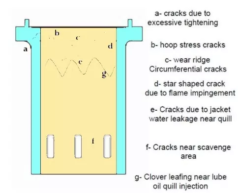
Cylinder Liner Failures
1. Crack through the Liner flange due to unequal or extra tightening of cylinder heads
2. Inadequate support causing hoop stress crack
3. New piston ring hitting the wear ridge causing circumferential Crack.
4. Flame intrusion causing a crazy crack
5. Cracks across the port bar due to overloading, unsatisfactory cooling, scavenge fire, poor installation of rubbing sealing ring.
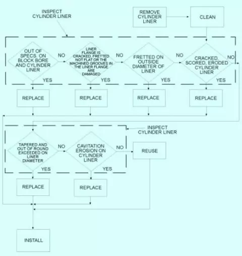
Cylinder Liner Repair Chart
Cylinder Liner Wear
- Abrasion is caused by hard particles produced due to lubricating oil film breakage.
- Acidic combustion products causing corrosion
- Metal to metal contact due to boundary lubrication causing scuffing break down.
- Hard particles derived from airborne dirt, ash contents carbon from combustion due to worn piston rings.
- Cold corrosion due to the sulfur turning into Acid at dew point.
The procedure of Cylinder Liner Removal
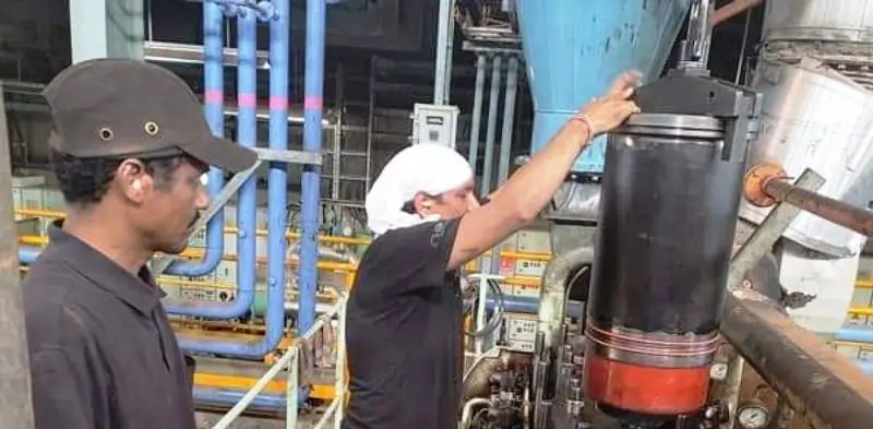
Follow the proper method for the removal of the liner. Cylinder liner will be damaged for not adopting the prescribed procedure and recommended tools by the engine manufacturer.
- Remove the piston and connecting rod
- Mark identification mark concerning cylinder block.
- Loosen the cylinder shoes of the cylinder liner lifting tool
- Put the shoes of the device at the bottom edge of liner
- Jack up the cylinder liner by turning the nut clockwise.
- Remove and discard the sealing ring (Tom’s back ring).
- Remove the cylinder liner lifting tool
- Remove and dump the cylinder sealing rings.
Important Note;- Always store or place the cylinder in a vertical direction. Else there may be a distortion of the liner. Also, note that the liner marking for the refitting in the unit’s exact location has been removed.
Cylinder liner cleaning procedure
Clean the liner with the following procedure.
- Clean the liner properly by using the recommended detergents ,hot water and cleaning brush.
- Rinse the cleaned liner with steam or hot water
- Dry the liner with dry compressed air.
- Smear the bore of the liner with fresh engine oil.
- Wait for 10 minutes for oil to work into the working surface.
- Wipe the cylinder bore with a clean paper towel
- Repeat the step 4 through 6 in case the black residue is observed on the towel
Inspection of Liner
Points to be observed while inspecting the cylinder liner
- Check the cylinder liner for cracks, fretting, and scoring.
- Scavenge ports opening with sharp edges,
- Formation of the edge at the top dead center position
- Liner surface with mechanical friction wear impressions and abrasive wear.
- Blow-by dark areas.
- Acidic and cold corrosion marks on the surface
- Lubrication opening with cracks and damages.
- Glazing of liner surface with a diminished indication of honing marks.
- Lube oil flow from lubrication ports
- Gauging of Liner bore for ovality and wear.
- Replace the Liner in case of any cracks, fretting, and scoring is detected.
- Inspect the cylinder liner for any cavitations erosion as per the below figure.
Gauging of the Cylinder liner
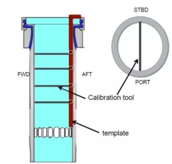
Gauging of the cylinder liner is to be carried out at regular
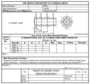
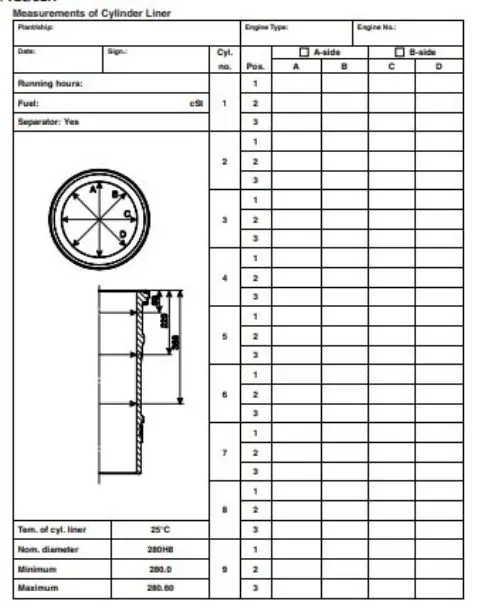
intervals mentioned in the OEM manual. Maintain the measurement record in the format below for future reference and wear rate calculation.
Inspect the liner thoroughly after proper cleaning. The temperature of the Liner bore measuring gauge and Liner should be identical.
In case of temperature difference exceeds or vice versa, then the following multiplying factor will be used.
Liner gauging report format
CYLINDER LINER HONING
In the course of continuous operation, Cylinder liners will be subjected to wear and tear. This wear is uniformly scattered. The highest wear develops between the turnaround points of the top and bottom piston rings. Generally, scuffing marks are observed at the area of the top piston reversal point. Most of the cylinder liners will be oval over long engine running hours.
Lubricating oil consumption will increase with the the additional effect of wear
A new cylinder liner received from the factory will have cross-hatch markings honed on the working surface. This roughness retains the lubricating oil required to maintain a uniformly distributed oil film between the piston rings’ turnaround points.
If the surface of the liner becomes glazed over a period of operation, the piston ring will easily break the oil film and cause extensive wear to the liner. The excess oil will not be retained and pass to the combustion chamber and burn off instead.
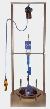
After gauging the liner, if the wear is found within the prescribed limits by the manufacturer, it will be possible to recondition the liner. This repair is possible by Honing process in the workshop.
Conclusion
Cylinder liners are essential for the efficiency and durability of modern engines. Proper installation and maintenance are crucial to ensure their optimal performance and longevity. By following the detailed installation procedures, addressing common issues promptly, and adhering to best maintenance practices, engineers can enhance engine reliability and minimize downtime. Understanding the role, types, and materials of cylinder liners, along with the significance of O-ring replacement and lubrication, empowers engineers to make informed decisions, ultimately leading to better engine performance and longevity. Stay proactive in your maintenance efforts, and your engines will thank you with years of reliable service.
