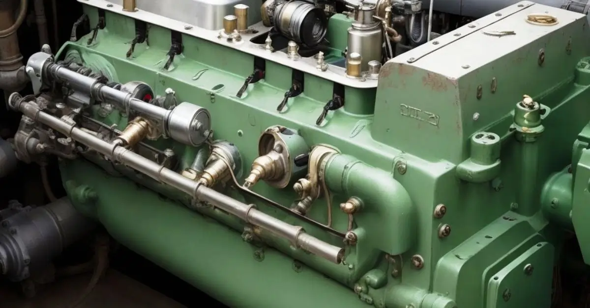
Diesel Engine Overhauling
The diesel engine – it’s the mighty heart of many vehicles and machines that keep our world in motion. Yet, like any heart, it occasionally needs a thorough checkup and sometimes even a full-on revival to maintain its strength and vitality. Many feel the same if you’ve ever thought fixing a diesel engine is tough. It’s a detailed job requiring careful work, time, and good knowledge of the engine’s parts. But fear not, for with the proper guidance, this seemingly overwhelming endeavor can be simplified and approached confidently.
Whether you’re a seasoned mechanic or just starting your journey, our top 10 tips on overhauling a diesel engine will empower you with the knowledge and techniques to breathe new life into these mechanical marvels. Read on and prepare to roll up those sleeves!
Reviving the Heartbeat: A Deep Dive into Overhauling a Diesel Engine
1. Understand Before You Undertake:
- Manufacturer’s Manuals: Every diesel engine, regardless of its similarities with others, has unique aspects. The manufacturer’s manual is tailored to the specific engine model, detailing its design, operational limits, and maintenance needs. By studying this, you set a strong foundation for the overhaul process. It’s akin to having a roadmap for a journey through unfamiliar terrain.
2. Organize and Prepare Your Workspace:
- Environment: A systematic workspace minimizes errors. Clear any unrelated items, ensuring ample space for the engine parts, tools, and movements.
- Containers and Labels: As you disassemble the engine, keep each part in labeled containers or trays. This strategy protects the components from contaminants and aids in a smoother reassembly.
3. Quality Tools Matter:
- Precision and Durability: High-quality tools are designed for accuracy and longevity. They reduce the likelihood of rounding off bolts, stripping threads, or causing unintentional damage, which can result from using subpar tools.
4. Detailed Documentation:
- Photographic Record: In our digital age, use your smartphone or a camera to document each disassembly step. This visual record is a reference, especially for complex assemblies or if the overhaul spans several days.
- Notes: Jotting down observations, measurements, and peculiarities can ensure that every part is addressed correctly during reassembly.
5. Prioritize Safety:
- Personal Protective Equipment (PPE): Wearing gloves protects against oils and sharp edges, safety glasses shield your eyes from debris, and ear protection is essential if using loud tools.
- Safe Practices: Ensure the engine has cooled down before starting work to avoid burns—disconnect batteries or other power sources to prevent unexpected startups.
6. Inspection Is Key:
- Component Analysis: Each component is critical, from the smallest bolt to the most significant gear. Check for signs of wear, such as thinning, deformities, cracks, or corrosion. Measure clearances and compare with the manufacturer’s specifications.
7. Seek Expertise:
- Collaborative Approach: No one knows everything. Engaging with experienced mechanics or joining online forums can provide insights or solutions to challenges that arise. Sometimes, the experience of others can offer shortcuts or prevent common mistakes.
8. Replacement Parts:
- Genuine over Generic: While generic parts might be tempting due to their lower costs, they may only sometimes match the quality, fit, or performance of the original features. Genuine parts are designed specifically for the engine, ensuring a longer lifespan and better performance.
9. Gradual Reassembly:
- Attention to Detail: As you put the engine back together, ensure each component is free of dirt and adequately lubricated. Tighten bolts and screws in the order and torque specified in the manual. This stepwise and careful approach ensures each part functions harmoniously with the rest.
10. Test Thoroughly:
- Controlled Environment: After reassembling, run the engine in a controlled setting. Listen for unusual sounds and monitor temperature, pressure, and other vital signs. Identifying and addressing issues now is crucial, ensuring the engine operates optimally once back in its primary setting.
By deepening our understanding of each step in the overhaul process, we appreciate the intricate dance of mechanics, science, and art that goes into rejuvenating a diesel engine. With patience, knowledge, and dedication, the rewards of a successful overhaul are well worth the effort: an engine that performs efficiently, reliably, and extends its service life.
Key Formulas for Diesel Engine Overhauling
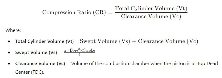
1. Compression Ratio Calculation
2. Bearing Clearance Measurement
Bearing Clearance (BC)=Bearing Inside Diameter (ID)−Shaft Outside Diameter (OD)
3. Piston-to-Bore Clearance
Piston-to-Bore Clearance (PBC)=Cylinder Bore Diameter (CBD)−Piston Diameter (PD)
4. Torque for Fasteners (Bolts and Nuts)
T=K×F×DT
Where:
- T = Torque applied to the bolt (Nm or ft-lbs).
- K = Torque coefficient or nut factor (typically 0.15 to 0.25).
- F = Clamping force or preload required (N or lbs).
- D = Nominal diameter of the bolt (m or in)
List of Spare parts for overhauling
Here is the table formatted as requested:
| Sr. No. | DESCRIPTION | Qty |
|---|---|---|
| CYLINDER HEAD | ||
| 01 | O Ring for valve guide. | 48 |
| 02 | Valve Guide (Inlet and exhaust) | 31 |
| 03 | O Ring | 34 |
| 04 | Valve Seat ring | 36 |
| 05 | O Ring for Cyl. Head. | 24 |
| 06 | Rockerarm complete | 1 |
| 07 | Rotocap complete (incl. items-490, 500, 512, 524) | 22 |
| 08 | Spring | 156 |
| 09 | Ball | 156 |
| 10 | Spring Washer | 12 |
| 11 | Retaining Ring | 4 |
| 12 | Valve Spendal inlet | 24 |
| 13 | Valve Spendal outlet | 24 |
| 14 | Gasket | 12 |
| 15 | Gasket | 12 |
| CYLINDERHEAD TOP COVER | ||
| 16 | Gasket | 12 |
| 17 | Gasket | 12 |
| PISTON AND CONNECTING ROD | ||
| 18 | Piston Ring (NEW TYPE) | 12 |
| 19 | Piston Ring (NEW TYPE) | 12 |
| 20 | Piston Ring (NEW TYPE) | 12 |
| 21 | Oil Scraper Ring | 12 |
| 22 | Connecting Rod Bearing 2/2 | 12 |
| 23 | Piston | 4 |
| 24 | Retaining Ring | 8 |
| 25 | Piston Pin | 12 |
| 26 | Bush for connecting rod | 12 |
| CYLINDER LINER AND WATER GUIDE JACKET | ||
| 27 | O Ring for Sleeve. | 24 |
| 28 | O Ring | 12 |
| 29 | O Ring | 144 |
| 30 | Sealing ring (Upper). | 12 |
| 31 | O Ring For Cyl. Liner. | 24 |
| 32 | Flame Rings | 12 |
| 33 | Sealing ring (Lower) | 12 |
| 34 | Hexagon Screw | 10 |
| 35 | Cylinder liner | 12 |
| 36 | Cooling water connection | 6 |
| CAMSHAFT AND CAMSHAFT BEARING | ||
| Camshaft Bearing Aft | 2 | |
| Camshaft Bearing | 12 | |
| ROLLER GUIDE AND PUSH RODS | ||
| 37 | Sealing ring | 48 |
| 38 | Roller guide for valve gear | 7 |
| 39 | Gasket | 24 |
| CRANKSHAFT | ||
| 40 | Locking Plate for Counterweight | 12 |
| 41 | Locking Plate for Counterweight | 0 |
| COVERS ON FRAME | ||
| 42 | Screw | 4 |
| 43 | O Ring for Camshaft door. | 12 |
| 44 | O Ring for crank case door. | 4 |
| 45 | O Ring for safety valve. | 6 |
| FRAME WITH MAIN BEARINGS | ||
| 46 | Main Bearing Shell 2/2 | 7 |
| 47 | Thrust washer 2/2 | 2 |
| 48 | Wear ring | 0 |
| CHARGING AIR COOLER | ||
| 49 | Gasket | 2 |
| 50 | Gasket | 2 |
| 51 | Gasket | 2 |
| 52 | Gasket | 2 |
| 53 | O RING | 2 |
| EXHAUST PIPE ARRANGEMENT | ||
| 54 | Packing Ring | 0 |
| 55 | Packing Ring | 1 |
| 56 | Gasket | 2 |
| 57 | Packing | 12 |
| 58 | O Ring | 14 |
| 59 | O Ring | 14 |
| AIR STARTER | ||
| 60 | Spare parts kit, | 0 |
| MAIN AIR STARTING VALVE | ||
| 61 | Spare Part Kit comprising | 1 |
| PRESSURE REDUCTION VALVE | ||
| 62 | Repair kit, | 1 |
| ELECTRIC TURNING GEAR | ||
| 63 | Ball Bearing | 0 |
| FUEL INJECTION PUMP | ||
| 64 | Kit comprising items | 12 |
| 65 | Shock Screw | 12 |
| 66 | Joint washer | 24 |
| 67 | Plunger and barrel incl. NRV | 12 |
| 68 | Circlip | 12 |
| 69 | O Ring | 24 |
| 70 | O Ring | 12 |
| 71 | Nozz Complete | 12 |
| 72 | Spring | 12 |
| 73 | Nut | 12 |
| 74 | Adjusting Screw | 2 |
| 75 | Screw cap | 1 |
| 76 | O Ring | 12 |
| 77 | Thrust Spindle | 12 |
| FUEL INJECTION PIPE | ||
| 78 | O Ring | 22 |
| 79 | O Ring | 11 |
| 80 | O Ring | 12 |
| 81 | Fuel injection pipe complete | 5 |
| 82 | Sealing rings | 12 |
| LUBRICATING OIL PUMP | ||
| 83 | Pump Housing | 1 |
| 83 | Bush | 5 |
| 84 | Self Locking Nut | 1 |
| 85 | Packing Ring | 2 |
| LUBRICATING OIL FILTER | ||
| 86 | Paper Element | 4 |
| HT FRESH WATER THERMOSTATIC VALVE | ||
| 87 | O Ring | 6 |
| 88 | Sleeve | 0 |
| 89 | Thermostatic element (Set point- 82°C) | 6 |
| 90 | Gasket | 1 |
| FRESH WATER PUMP LT | ||
| 91 | Pump Complete | 1 |
| 91 | Rotating Packing | 1 |
| 92 | Oil Sealing ring | 1 |
| 93 | Ball bearing | 2 |
| 94 | Gasket | 1 |
| 95 | Gasket | 1 |
| 96 | Lock Nut | 1 |
| 97 | Lock Nut | 1 |
| FRESH WATER PUMP HT | ||
| 98 | Rotating Packing | 1 |
Detailed Major Overhauling Procedures:
Crankshaft:
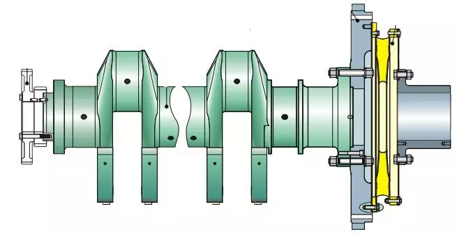
Crankshaft Deflection Measurement: A Comprehensive Guide
The crankshaft is a vital component in an engine, responsible for converting the linear motion of the pistons into rotational motion that drives the wheels. Due to its central role and the forces it endures, ensuring its straightness is crucial. One way to ascertain this is through deflection measurement.
What is Crankshaft Deflection?
Crankshaft deflection refers to the minute bend or deviation from a straight line that a crankshaft might undergo due to operational stresses. Over time, this can lead to uneven wear and potential engine damage. Monitoring and measuring this deflection helps in the early detection of issues and can guide corrective measures.
Step-by-Step Measurement Process:
- Setting Up:
- Engine Preparation: Ensure the engine is turned off and cooled down before starting. This ensures safety and accurate measurements.
- Dial Indicator: This precision instrument measures small distances or movements. Securely attach the dial indicator to the engine block, ensuring its probe touches a smooth surface of the crankshaft, usually the main bearing or journal.
- Rotating the Crankshaft:
- Manual Rotation: Rotate the crankshaft using appropriate tools or by engaging the engine’s manual turning mechanism. Ensure smooth, steady rotation to get accurate readings.
- Observing the Dial Indicator: As the crankshaft turns, the dial indicator’s needle will move, representing the deflection. A perfectly straight crankshaft would see little to no movement. However, some movement is expected due to the inherent design of the crankshaft and its bearings.
- Recording and Analysis:
- Taking Measurements: Observe the maximum and minimum readings on the dial indicator as you rotate the crankshaft. The difference between these readings is the deflection measurement.
- Comparison with Manufacturer’s Specifications: Refer to the engine’s service or repair manual once you have the deflection measurement. Manufacturers will typically provide acceptable deflection limits. Compare your recorded measurement with these values.
- Interpreting Results: The crankshaft is in good condition if the deflection is within the manufacturer’s limits. If it exceeds these limits, it indicates potential issues such as bearing wear, crankshaft wear, or misalignment, which require further investigation and possible corrective actions.
Cylinder Head Overhaul:
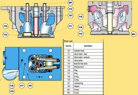
Cylinder Head Overhaul: A Comprehensive Step-by-Step Guide
Cylinder Head Overhaul: A Comprehensive Step-by-Step Guide
The engine’s cylinder head is a crucial component. Spark plugs and valves are stored there. Due to the high heat and pressure it encounters may eventually require maintenance or “overhaul.” Here is a detailed explanation of how to accomplish it:
Removal of the Cylinder Head:
- Safety First: Ensure the engine is switched off, cooled down, and disconnected from any power source.
- Access: Remove any components obstructing access to the cylinder head, such as the intake manifold, exhaust manifold, or any wiring and connections.
- Lifting Equipment: Due to the weight and delicacy of the cylinder head, use appropriate lifting equipment, such as an engine hoist or crane. Attach the lifting tools to designated points on the cylinder head.
- Loosen & Lift: Gradually loosen the cylinder head bolts in the recommended sequence (usually from the outer bolts moving inward). Once all bolts are removed, carefully lift the cylinder head off the engine block.
Disassembly:
- Component Removal: Using the correct tools, remove the valves, springs, retainers, and injectors. Organize these components systematically to facilitate easy reassembly later.
Cleaning:
- Degreasing: Apply a high-quality degreasing agent to all components to remove oil, carbon deposits, and other contaminants. Ensure thorough coverage and let it soak as per the product’s instructions.
- Ultrasonic Bath (Optional but Recommended): An ultrasonic bath uses sound waves to thoroughly clean components at a microscopic level. Place the parts in the tub, ensuring they are fully submerged, and run the machine for the recommended duration.
Inspection:
- Visual Check: Examine every component closely. Look for visible signs of wear, cracks, or damage. Please pay special attention to the cylinder head’s surface, ensuring it’s flat and free of imperfections.
- Magnifying Tools: Using magnifying glasses or specialized inspection equipment can help spot minute cracks or defects that are otherwise invisible to the naked eye.
Measurement:
- Valve Guides and Seats: Using precision tools like micrometers or calipers, measure the dimensions of the valve guides and seats. Check for any irregularities or excessive wear.
- Comparison: Refer to the manufacturer’s manual for the engine. It will provide standard measurements for these components. Compare your readings with these standard values to determine if any components need replacement or reconditioning.
Reassembly:
- Organized Approach: Refer to your earlier organization of components. This will guide a systematic reassembly.
- Component Fitting: Reinstall the valves, springs, retainers, and injectors. Ensure each part fits perfectly, without any force or obstruction. Proper seating of components is crucial to the engine’s performance.
Pressure Test:
- Sealing: Before the test, seal off all water or coolant passages in the cylinder head. This can be done using specialized plugs or caps.
- Introducing Pressure: Connect the cylinder head to a pressure testing machine. Introduce pressurized air or water (per the testing equipment’s guidelines).
- Observation: Monitor the pressure gauge. A well-sealed cylinder head will maintain consistent pressure. If there’s a drop, it indicates a leak. Listen and look for visible or audible signs of air or water escaping.
Valves & Components:
- Renewal & Grinding:
- Remove old valves, rotators, and guides.
- Clean and inspect the valve seats.
- Use a grinding tool to refine the valve seats, ensuring a snug fit of the valves.
- Install the new components, ensuring they are secured in place.
Connecting Rods:
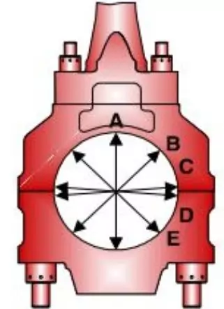
- Connecting Rods: Inspection & Measurements Detailed Guide
Connecting rods act as crucial intermediaries in an engine, linking the piston to the crankshaft. Their integrity ensures the engine operates smoothly, making their inspection and measurement a critical part of engine maintenance.
1. Detachment from the Crankshaft:
- Preparation: Before you start, ensure the engine is switched off and cooled down for safety.
- Positioning: Rotate the crankshaft to access the connecting rod cap nuts or bolts.
- Loosening and Removal: Gradually loosen and remove the cap nuts or bolts. Carefully separate the connecting rod from the crankshaft.
2. Piston Removal:
- Circlip Removal: A circlip holds Many pistons onto the connecting rod. Remove this circlip using circlip pliers.
- Pushing out the Pin: With the circlip removed, you can push out the wrist pin (or gudgeon pin), which holds the piston to the connecting rod. This might require slight pressure or gentle tapping, but be careful not to damage the piston or rod.
3. Cleaning:
- Degreasing Agent: Use a high-quality degreaser to clean off oil, carbon deposits, and other contaminants from the connecting rods and pistons.
- Brushing: Utilize soft brushes to clean hard-to-reach areas and remove stubborn deposits.
4. Measurement using a Micrometer:
- Small-end Pin Diameter: The smaller end of the connecting rod, which attaches to the piston, is known as the small-end. Using a micrometer, measure the diameter of this end where the wrist pin goes through.
- Big-end Bore Diameter: This is the larger end of the connecting rod that attaches to the crankshaft. Measure its inner diameter using a micrometer.
5. Comparing Measurements:
- Manufacturer’s Manual: Refer to the engine’s manual once you have your measurements. This will provide standard measurements for the connecting rods.
- Analysis: If your measurements deviate from the standard specifications, it might indicate wear and the potential need for replacements or machining.
6. Visual Inspection for Cracks:
- Close Observation: Examine the connecting rod, especially the big-end housing, for any visible cracks or signs of damage.
- Magnifying Tools: A magnifying glass or other specialized equipment can help spot minute defects for a detailed inspection.
7. Reassembly and Reinstallation:
- Pistons and Rods: Reconnect the piston to the connecting rod by sliding in the wrist pin and securing it with the circlip.
- Engine Installation: Position the big end of the connecting rod onto the crankshaft journal. Ensure proper alignment, then fasten the connecting rod cap using the nuts or bolts, tightening them to the manufacturer’s specified torque.
Pistons:
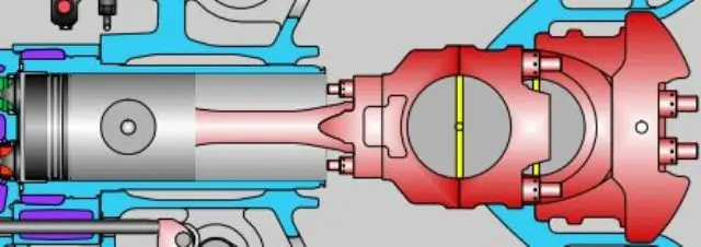
- Maintenance Procedure:
- Remove piston rings.
- Clean pistons using a degreasing agent.
- Inspect for cracks, scoring, or any other damage.
- Measure the piston’s diameter and compare it with manufacturer specifications.
- Install new piston rings, ensuring they fit securely.
Crank Pin:
- Cleaning & Inspection:
- Clean the crank pin using appropriate cleaning agents.
- Inspect for wear, scoring, or damage.
- Measure the diameter and compare it with the manufacturer’s specifications.
Cylinder Liner:
- Replacement:
- Remove the old cylinder liner by pulling it out using specialized tools.
- Clean the cylinder block where the liner sits.
- Install the new cylinder liner, ensuring it’s seated properly.
Main Bearings:
- Maintenance:
- Remove main bearing caps.
- Take out the old bearings.
- Clean the bearing housing and inspect for uneven wear or scoring.
- Place the new bearings and secure the bearing caps back.
Thrust Bearing:
- Axial Clearance Measurement:
- With the crankshaft in place, use a dial indicator to measure the forward and backward movement of the crankshaft.
- Record the measurements and ensure they are within manufacturer specifications.
Camshaft Bearings:
- Inspection & Measurement:
- Remove the camshaft from the engine.
- Clean and inspect the camshaft and its bearings.
- Measure the bearing clearances using a plastic gauge or similar tools.
- Ensure measurements are within specifications.
Timing Gears:
- Backlash Assessment:
- Using a dial indicator, measure the play between the gear teeth.
- Compare the measurements to manufacturer specifications.
LO Pump Overhaul:
- Standard Maintenance:
- Disassemble the pump.
- Clean all parts and inspect for wear or damage.
- Replace any defective components.
- Reassemble the pump with new seals and fasteners, ensuring no leaks.
CW Pump Overhaul:
- Similar to the LO pump overhaul procedure.
Fuel Injection Pump:
- Overhaul Procedure:
- Disassemble the fuel injection pump using appropriate tools, ensuring all components are kept for reassembly.
- Clean all parts using a suitable cleaning solution to remove fuel residues and contaminants.
- Inspect components like plunger elements and valves for wear, damage, or deformities.
- Adjust any misalignments found during the inspection process.
- Replace worn-out or damaged components, such as plunger elements and valves, with new ones.
- Reassemble the fuel injection pump, ensuring all components are in their correct positions, and there are no leaks when the pump is pressurized.
Roller Guide for Fuel Injection Pump:
- Standard Checks:
- Carefully disassemble the roller guide.
- Clean all components using an appropriate cleaning agent to remove residues or contaminants.
- Inspect the roller guide for signs of wear, scoring, or other damage.
- Measure the dimensions of key components to ensure they’re within the manufacturer’s specifications.
- Reassemble the roller guide, ensuring smooth operation and correct alignment.
Fuel Injection Valves:
- Maintenance:
- Disassemble the fuel injection valves.
- Clean the components to remove carbon deposits and contaminants.
- Inspect the valves for wear, especially at the nozzle end.
- Adjust components as necessary to ensure optimal operation.
- If wear is detected on the nozzles or if they fail to produce the correct spray pattern, replace them.
- Reassemble the fuel injection valves, ensuring tight seals and proper alignment.
TC Cartridge & Air Cooler:
TC Cartridge Replacement:
- Isolate the turbocharger (TC) from the system and ensure safety precautions are followed.
- Disassemble the turbocharger to access the cartridge.
- Remove the old cartridge and replace it with a new one, providing it fits securely and correctly.
- Reassemble the turbocharger, checking for any abnormalities in rotation or alignment.
Air Cooler Maintenance:
- Disconnect the TC air cooler from the system.
- Clean the cooler’s interior using appropriate cleaning agents to remove oil, carbon deposits, and other contaminants.
- Inspect the cooler for signs of damage, leaks, or blockages.
- Reconnect the air cooler to the system and ensure no leaks under operational pressure.
By following these detailed procedures, you should be able to thoroughly overhaul the engine components mentioned in the scope of work. Always consult the engine’s service manual and adhere to safety procedures while performing any work.
FAQ on “How to Overhaul a Diesel Engine”
Q1: What is the primary purpose of overhauling a diesel engine?
A1: To restore the engine’s performance, extend its lifespan, and ensure optimal efficiency.
Q2: Do I always need specialized tools for a diesel engine overhaul?
A2: Yes, using the right tools ensures precision and avoids potential damage during the overhaul.
Q3: How often should a diesel engine undergo an overhaul?
A3: It varies based on usage and engine condition, but generally, an engine should be overhauled after reaching its recommended operational hours or mileage.
Q4: Is a diesel engine overhaul only about replacing parts?
A4: No, it also involves cleaning, inspecting, and potentially repairing or refurbishing existing components.
Blog Post Conclusion
Giving a diesel engine a thorough overhaul isn’t just about boosting its power; it’s about making it last longer, keeping it safe, and getting the best fuel results. Even though overhauling might feel overwhelming initially, with the right tools and a bit of guidance, it becomes a rewarding experience. In the same way that an experienced artist refreshes an old painting, someone passionate about engines can rejuvenate a diesel engine, making it purr with new energy. Always remember that an engine’s lifespan is influenced by its build and how it’s looked after. Until our subsequent discussion, keep those engines humming!
