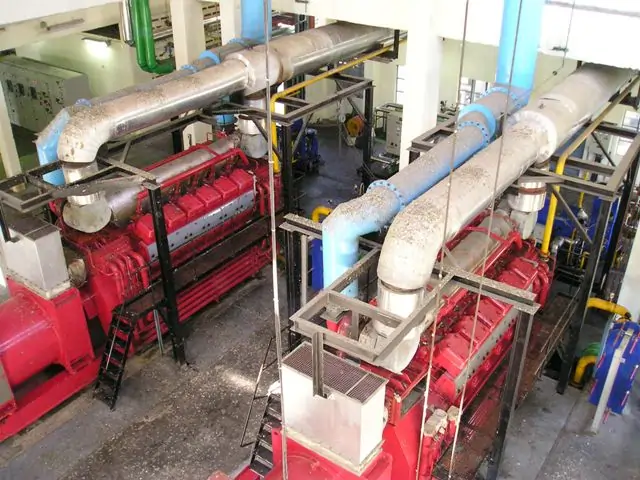
What Is Diesel Power Plant
Are diesel power plants on your mind? Imagine them as factories that use diesel engines to create electricity. Electricity generated by these power plants is supplied for running the industries, Domestic usage, and emergency supply to hospitals and other life-saving utilities. Diesel Power Plants work by burning diesel fuel in engines. In this way produced energy is turned into Electricity. Diesel Power Plants are known for their flexibility and quick response time – they can start generating electricity within minutes. This makes them ideal for situations when power is needed urgently. Whether it’s a remote area or a backup power source for emergencies, Diesel Power Plants play a vital role. Continue reading to learn more about Diesel Power Plants
Essential Components of Diesel Power Plants
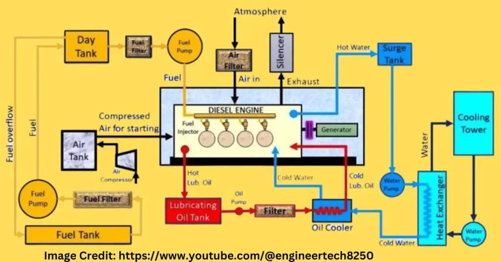
Let’s talk about the important parts of Diesel Power Plants, focusing on the main engine:
- Prime Mover (Engine): This is the heart of the plant, where the real energy is created.
- Alternator (Generator): It’s like the converter that changes mechanical energy into electricity.
- Starting and Stopping System: Just like turning on and off a machine, this system gets the engine going.
- Air System: Engines need air to breathe, and this system provides it.
- Lubricating Oil System: Engines have moving parts, and this system keeps them running smoothly.
- Intake System: It brings air into the engine for the combustion process.
- Fuel System: Like giving food to an engine, this system supplies diesel fuel.
- Exhaust System: After creating power, the engine needs a way to release gases.
- Cooling System: Engines can get hot, so this system keeps them from overheating.
- Control and Governing System: It’s like the brain of the plant, controlling how everything works together.
Engine
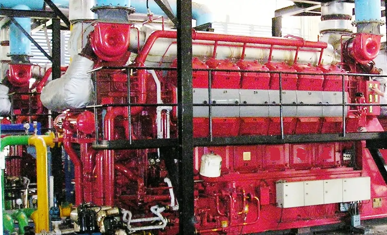
Let’s talk about the main part of a power plant – the Engine (Prime Mover). This is like the heart of the plant. It takes heat energy and changes it into moving energy. Just like our muscles move our bodies, the prime mover makes the power plant work. It’s what gets everything going and generates the power we use.
For generating power, we use a type of engine called a “four-stroke engine.” These engines have four steps to make power. They are great for power plants because they use less fuel, have a good way to keep them lubricated, and they are flexible. They also make less noise and are easy to cool. Plus, they’re efficient and can turn heat into power really well. So, these engines are like the superheroes of power plants!
Fuel System of diesel power plants
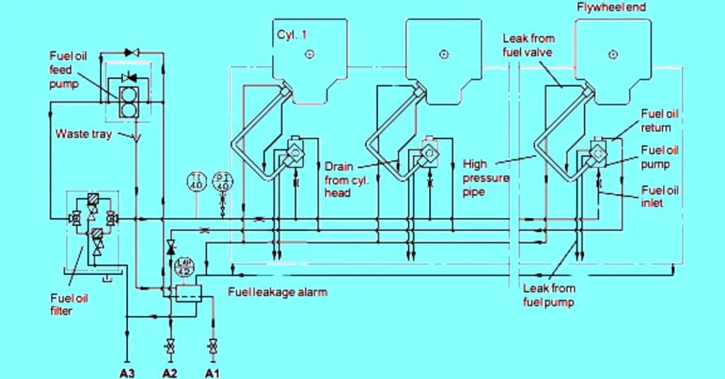
Fuel Systems of a Diesel Power Plant
1. Fuel Supply system
2. Fuel Injection system
Fuel Supply system
The fuel transfer system receives and stores the fuel in the tanks. Heaters are provided in the HFO storage tanks to maintain the correct pour point. From the storage tanks, the fuel continuously circulates. From the circulation system, fuel is transferred to fuel settling tanks through a controlled valve. The control valve supplies the fuel to the settling tank as per the required quantity. Settling of the solid and water takes place in the settling tank.
From the Fuel settling tank, fuel is supplied to the fuel treatment units. Oil is pumped to the daily service tanks after the purifying process. Fuel circulates to the mixing unit via the three-way valve. Consumption of fuel is metered through a flow meter installed in the system. Fuel supply pumps supply the fuel to the engine-driven fuel pump. From the engine-driven pump, fuel is supplied to the fuel injection system through fuel filters.
For the efficient combustion of the fuel, the temperature of the fuel is monitored by the viscosity meter provided in the fuel booster system. A pressure-regulating valve installed in the system will regulate the fuel supply at constant pressure to the engine-driven pump.
A diesel tank is incorporated into the system and is connected to the fuel supply system via a three-way cock. In the mixing tank, the circulated fuel is collected and supplied to the day tank.
The fuel system is equipped with two critical safety devices under
- A valve was installed at a remote place to close the fuel system supply in the event of a fire.
- Low fuel level in the tank.
Fuel Injection system
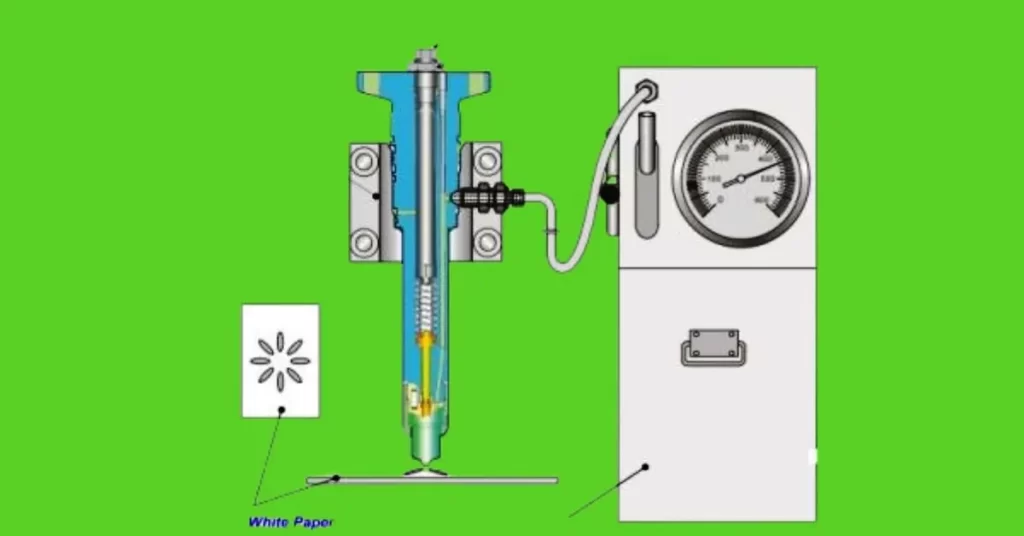
Let us discuss the fuel injection system which consists of fuel Injection Pumps and Fuel Injection Valves..”
Imagine the fuel injection system as a way to give the engine the exact amount of fuel it needs, exactly when it needs it. It’s like a super precise delivery system. The main players in this system are the fuel injection pump and the fuel injectors.
The fuel injection pump acts like the leader of a musical band. It sends just the right amount of fuel to each injector. And these injectors are like small taps that spray fuel into the engine in a special way.
When these parts work together, the engine gets the perfect fuel amount to create power really efficiently. It’s like having a finely tuned instrument playing a flawless tune. The Fuel injection system is a responsible and crucial system of a Diesel Power Plant which ensures the ideal performance and smooth operation.
Air Intake System
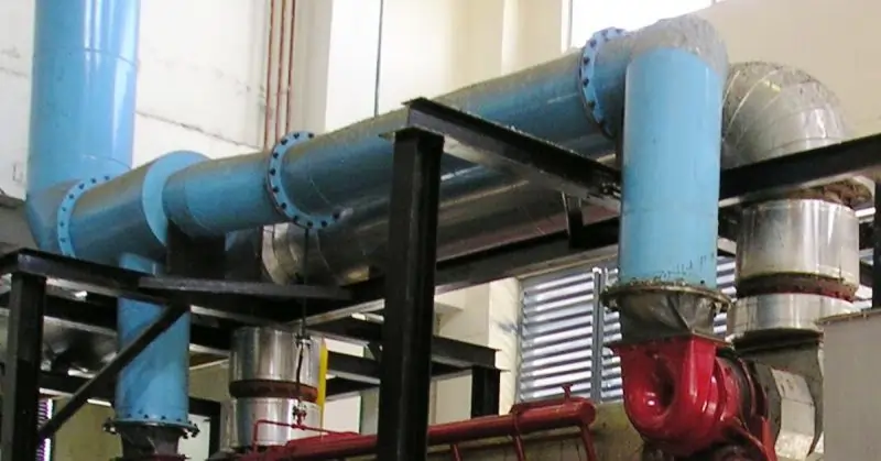
Let’s break down the “Air Intake System” and its components:
The Air Intake System is made up of a few important parts that help the engine get the air it needs to work properly. These parts are:
- Air Intake Ducting: This is like a special pathway that helps bring in the air from outside.
- Silencer: This part helps reduce the noise that comes from the air as it flows into the engine.
- Air Cleaner: The air cleaner is like a filter that makes sure the air going into the engine is clean and doesn’t have any dirt or impurities.
- Flexible Connections: These are like bendy parts that help the system fit together nicely.
By arranging these parts, the air intake area is placed far from the engine, so the noise from the air isn’t too loud. The filters in the system make sure that the engine doesn’t get any dirt or stuff from the air that could harm it.
The design of the air system is made to be small to reduce friction and costs. The filter is designed to collect dust but is easy to clean and doesn’t slow down the airflow much. The air system also has a silencer and a special type of filter to keep things running smoothly.
Flue Gas System
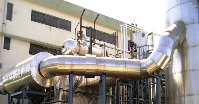
Let’s break down the “Flue Gas System” and its components:
When the engine’s exhaust valves let out gases, these gases go into something called a “gas receiver.” In the receiver, the gases are balanced so they don’t push too hard or too softly. Then, these gases go to a turbocharger.
After that, the gases come out of the turbocharger and go into the “Exhaust Gas System.” This system includes a “spark arrester silencer,” which is like a part that makes the noise and sparks from the exhaust quieter and safer. There’s also a pipe that carries the exhaust gases, and it’s supported and covered with special insulation.
For some power plants, there’s something called a “Waste Heat Recovery Boiler.” The exhaust pipe connects to this boiler to use the extra heat. If the power plant doesn’t have this boiler, the exhaust system goes straight to a tall pipe called an “exhaust stack.”
Sometimes, there’s a “heat recovery unit” in the flue gas system. This unit collects extra heat to make steam. This steam can be used for things like cooling or heating.
The exhaust silencer does three important jobs: it makes the exhaust gas noise less, it stops sparks from coming out, and it collects extra heat. The silencer works like a spinning fan with blades inside to make things quiet and safe.
Engine cooling water system
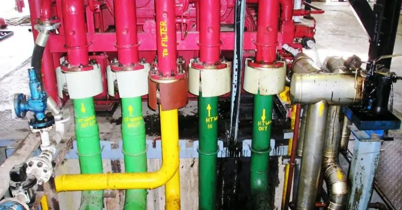
Let’s talk about the “Engine Cooling Water System.” There are two types of systems in this: the “Low-Temperature Cooling Water System” and the “High-Temperature Cooling Water System.”
The Low-Temperature Cooling Water System is like the cooler water that helps keep the engine from getting too hot. The High-Temperature Cooling Water System is for the hotter parts of the engine that need more cooling to work well. These systems together make sure the engine stays at the right temperature and works smoothly.
LT water system (Low-temperature system)
Let’s talk about the “Low-Temperature Water System” or LT water system. This system helps keep things cool in the engine. A pump circulates the LT water through the charge air cooler and the lube oil cooler.
The LT system is designed to keep the freshwater temperature lower than 36°C. This is important so that the charge air, which is the air going into the engine, doesn’t get too hot. With the controlled water temperature engine will work well and will remain in good condition.
High-temperature cooling water system (HT circuit)
let’s talk about the “High-Temperature Water System” or HT water system. This system helps cool down important parts of the engine. The water goes through the first stage of the charge air cooler before it goes into the cooling water jackets and cylinder heads. It’s like a cooling process to make sure the engine doesn’t get too hot and can work properly. The water is moved by a pump called the Temperature Circulating Pump. The optimum temperature will let the engine work satisfactorily with the best performance.
Starting Air System
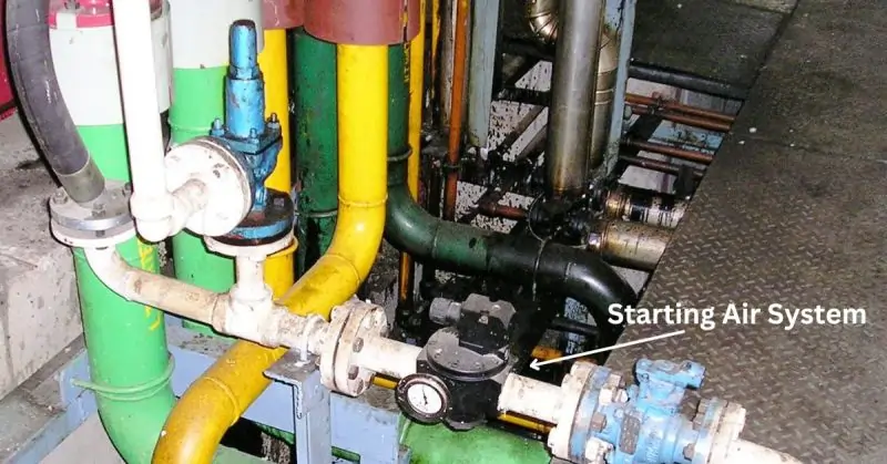
The compressed air is supplied from the Starting Air Bottle. The air passes to the Dirt separator and is further provided to the engine starting equipment at a pressure of 8.5 bars to 10 Bars.
- Direct Air Starting system- In this system, Compressed air is directly supplied to Engine cylinders at a pressure of 30 bars. The starting air enters the cylinders as per the firing order for the starting sequence of the engine and the engine starts, as soon as the engine gains the starting speed.
- Starting Motors: – In this system, starting air is supplied to the starting Air Motor at a pressure of 8.5 Bars to 10 bars. The flywheel is rotated at a starting speed by a starting Air motor.
- Starting Control System– Starting air to the starting motor is supplied through the Solenoid valve operating as per the signals from the starting control system. The system is also provided with an emergency starting valve that can be used manually to start the engine in auto system failure.
Lubricating Oil System
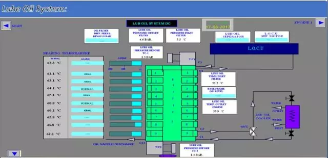
The lubrication system provides the lubricating oil to the moving parts of an engine. The lubricating oil provides the oil film between the moving parts and prevents the parts from generating heat due to friction. The secondary role of the lubricating oil is to clean the amounts of combustion impurities deposited in the parts.
In the dry sump type engine, oil suction by the lube oil pump is taken from a separate tank. In the wet sump type engine, the lube oil pump takes suction from the engine sump. The pump supplies the oil to the engine through the lube oil cooler, the Thermostatic valve, and full-flow filters. In the engine, the oil circulates through many branch pipes to supply the various parts asunder..
- Main and conrod bearings
- Piston cooling
- Cooling of the piston.
- Valve gears mechanism for the lubrication of rocker arms.
- Lubrication system for the camshaft components
- Other auxiliaries engine units like, Turbocharger, Governor, Pumps, and Valve-gear trains.
A bypass oil cyclone-type filter is installed on the engine to clean the impurities of lubricating oil.
Pre-Lubrication Pump
A pre-lubrication pump, also known as a lube oil priming pump, is a critical component in modern engine systems. It provides lubricating oil before the engine starts, ensuring that all moving parts are adequately lubricated and protected from wear and tear. This process significantly improves the longevity and performance of the engine by reducing friction and preventing damage during the initial start-up phase.
Function and Operation
The primary function of the pre-lubrication pump is to supply lubricating oil to the engine’s moving parts before the engine is started. This is crucial because, during the initial start-up, there is a period where the engine’s internal lubricating system has not yet built up sufficient oil pressure to ensure proper lubrication. The pre-lubrication pump addresses this gap by:
- Supplying Lubricating Oil: The pre-lubrication pump activates before the engine starts, pumping oil to critical components such as bearings, pistons, and camshafts.
- Reducing Boundary Lubrication: By providing oil before start-up, the pump minimizes the time the engine operates under boundary lubrication conditions, where metal-to-metal contact occurs, leading to increased wear.
- Facilitating Hydrodynamic Lubrication: The oil supplied by the pre-lubrication pump quickly establishes a hydrodynamic lubrication regime, where a full oil film separates moving surfaces, significantly reducing friction and wear.
Importance of Pre-Lubrication
The pre-lubrication process is vital for several reasons:
- Wear Reduction: By ensuring that all engine components are lubricated before start-up, the pre-lubrication pump reduces wear and tear, extending the engine’s lifespan.
- Smooth Start-Up: The immediate availability of lubricating oil leads to smoother engine start-ups, reducing mechanical stress on components.
- Engine Protection: The pump provides a crucial layer of protection against initial start-up wear, which is when most engine damage occurs due to insufficient lubrication.
Types of Pre-Lubrication Pumps
Pre-lubrication pumps come in various types and designs, tailored to meet the specific needs of different engines:
- Electric Pre-Lubrication Pumps: These are commonly used in modern engines and are powered by the vehicle’s electrical system. They offer precise control over oil flow and pressure.
- Mechanical Pre-Lubrication Pumps: Driven by the engine itself, these pumps are often used in heavy-duty applications where robust and reliable lubrication is essential.
- Pneumatic Pre-Lubrication Pumps: These pumps use compressed air to deliver oil and are typically used in industrial and marine applications.
Benefits of Pre-Lubrication Pumps
The benefits of using a pre-lubrication pump in an engine system are numerous:
- Extended Engine Life: By minimizing start-up wear, pre-lubrication pumps help extend the overall life of the engine.
- Improved Performance: Proper lubrication from the moment the engine starts ensures optimal performance and efficiency.
- Reduced Maintenance Costs: Engines with pre-lubrication pumps experience fewer breakdowns and require less frequent maintenance, leading to cost savings over time.
- Enhanced Reliability: Pre-lubrication pumps contribute to the overall reliability of the engine, making it more dependable in various operating conditions.
Alternators
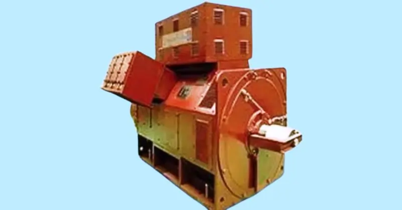
Alternators are extraordinary machines that perform the essential task of converting mechanical energy into electrical power. Here’s an in-depth look at how they operate, the different types, and their attributes.
How Alternators Operate
Mechanical energy is produced when an engine in a power plant rotates. This rotational energy is harnessed by the alternator, which then transforms it into electrical power. The process involves the following steps:
- Mechanical Input: An engine or turbine drives the alternator’s rotor, creating mechanical energy.
- Magnetic Field Generation: As the rotor spins, it creates a rotating magnetic field.
- Electromagnetic Induction: The rotating magnetic field induces an alternating current (AC) in the stator windings, generating electricity.
Types of Alternators
There are various types of alternators designed for different applications, each with unique characteristics.
- Synchronous Alternator: This type generates electricity that matches the power grid’s frequency. It operates in sync with the grid, making it ideal for power plants supplying electricity to the grid.
- Asynchronous Alternator (Induction Generator): Unlike synchronous alternators, asynchronous alternators do not need to match the grid’s frequency. They are often used in applications where precise frequency control is less critical.
- Marine Application Alternator: These are designed for use on ships and boats, providing reliable power in marine environments. They are built to withstand harsh conditions such as saltwater corrosion and high humidity.
- Locomotive Diesel Electric Alternator: Used in diesel-electric locomotives, these alternators convert mechanical energy from the diesel engine into electrical power to drive the traction motors.
- Brushless Type Alternator: These alternators eliminate the need for brushes by using a combination of rotating and stationary magnetic fields. They are known for their durability and low maintenance.
- Radio Alternators: Historically used in early radio transmission, these alternators generate high-frequency AC for long-distance communication.
Attributes of Alternators
Alternators have several key attributes that define their performance and efficiency:
- Current and Alternator Speeds: The current produced by an alternator is directly proportional to its rotational speed. As the speed increases, the output current also increases.
- Efficiency and Speed: The efficiency of an alternator is proportional to its speed. Higher speeds generally result in higher efficiency, making the conversion process more effective.
- Current and Temperature Rise: The relationship between current and temperature rise is inversely proportional. As the current increases, the temperature of the alternator components rises. Efficient cooling systems are essential to manage this heat and maintain performance.
Control and Governing system of diesel power plants
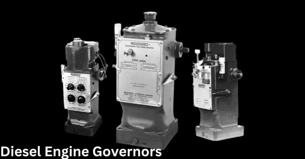
The pre-control and governing system in power generation is crucial for maintaining stable and high-quality electrical output. These systems ensure that generators operate efficiently and effectively, adjusting to varying load requirements and maintaining consistent frequency and voltage levels. This advanced description explores why these systems are required, their functions, and their impact on power quality and generator performance.
Why is a Pre-Control and Governing System Required?
The load on a generator is never constant; it fluctuates based on the demand for power. Without a robust pre-control and governing system, these fluctuations can lead to several issues:
- Oscillating Frequency: Variations in load can cause the generator’s frequency to oscillate, leading to an unstable power supply.
- Poor Quality Supply: Without proper adjustments, the generator may supply power of poor quality, characterized by inconsistent voltage and frequency.
- Uncompromised Adjustments: Lack of precise control mechanisms results in inefficient responses to load changes, degrading overall performance.
Ensuring Stable Power Output
A well-designed pre-control and governing system addresses these issues by:
- Maintaining Constant Frequency: The system continuously adjusts the generator’s operation to maintain a constant frequency, ensuring that the power generated meets the system’s requirements. This is crucial because frequency stability is a key indicator of power quality.
- Regulating Voltage: In addition to frequency, the system also controls voltage levels. Proper voltage regulation is essential for the steady and reliable performance of electrical devices and systems.
- Quality Power Supply: By managing both frequency and voltage, the pre-control and governing system ensures a high-quality power supply that is consistent and reliable.
Components and Functionality
The pre-control and governing system consists of several components that work together to regulate generator performance:
- Frequency Control: This component monitors the generator’s frequency and makes real-time adjustments to the engine speed to keep the frequency stable.
- Voltage Regulation: Voltage regulators adjust the generator’s output voltage, compensating for load changes and ensuring that the voltage remains within desired limits.
- Load Adjustment: The system dynamically adjusts the power output based on load requirements, ensuring that the generator operates efficiently under varying conditions.
- Engine Governing: The governing system controls the engine’s fuel supply and speed, administering frequency and power output to match the system’s demand.
Impact on Power Quality and Performance
The quality of power generated by a system depends significantly on maintaining proper frequency and voltage. A pre-control and governing system has several positive impacts:
- Steady Output: By ensuring stable frequency and voltage, the system provides a steady electrical output, which is crucial for the reliable operation of connected devices.
- Improved Performance: Generators equipped with advanced control and governing systems perform more efficiently and effectively, with reduced wear and tear on components.
- Enhanced Safety: Stable power generation reduces the risk of electrical faults and failures, enhancing overall system safety.
Importance of Engine Governing Systems
The engine governing system plays a pivotal role in the overall management of generator performance:
- Frequency Administration: By controlling engine speed, the governing system ensures that the generator maintains a constant frequency, crucial for synchronous operations with the power grid.
- Power Output Management: The governing system adjusts the engine’s fuel supply to match the load demand, ensuring efficient fuel usage and optimal power output.
Diesel Power plant Speed control
The speed control system in a diesel power plant is essential for managing the engine’s performance and ensuring a consistent and reliable power output. This system maintains a constant shaft speed across all loads and provides a steady fuel supply, which is crucial for the efficient operation of the engine. This detailed description explores the components and functions of the diesel power plant speed control system, emphasizing its role in engine control, monitoring, and safety.
Constant Shaft Speed Management
A critical aspect of the diesel power plant speed control system is its ability to maintain a constant shaft speed, regardless of the load. This is achieved through:
- Load Sensing: The system continuously monitors the load on the generator.
- Speed Adjustment: Based on load changes, the system adjusts the engine speed to maintain a constant shaft speed, ensuring stable power generation.
Steady Fuel Supply Maintenance
To ensure the engine operates smoothly and efficiently, the speed control system also regulates the fuel supply:
- Fuel Control: The system modulates the fuel injection based on the engine’s speed and load conditions.
- Optimal Combustion: By maintaining a steady fuel supply, the system ensures optimal combustion, reducing emissions and improving fuel efficiency.
Engine Control System (ECS)
The Engine Control System (ECS) in diesel power plants is a sophisticated and smart system installed independently on each generator set. It performs various functions, including:
- Smart Functions: The ECS is capable of advanced engine control functions, such as automated start/stop, load sharing, and synchronization.
- Interface with Plant System: The ECS interfaces seamlessly with the overall plant system, ensuring integrated operation and monitoring.
Monitoring and Safety Functions
The ECS is also responsible for the complete monitoring and safety functions of the engine:
- Operation Monitoring: The system continuously monitors engine parameters such as temperature, pressure, and speed, ensuring optimal performance.
- Safety Management: The ECS manages safety functions, including emergency shutdowns, alarm notifications, and fault diagnostics, protecting the engine from damage.
- Remote Connectivity: The ECS is connected to external systems, enabling remote monitoring and control. This connectivity allows operators to manage the engine from a centralized control room, enhancing operational efficiency.
Main Units of the Speed Control System
The speed control system comprises several main units, each playing a critical role in its operation:
- Panel for ECS (Engine Control System):
- Function: The ECS panel is the central unit of the engine control system, managing the primary functions of the engine.
- Connectivity: It is connected to both internal and external systems, providing comprehensive monitoring and control capabilities.
- User Interface: Operators can monitor engine status and manage operations through a touch screen on the ECS panel, ensuring ease of use and accessibility.
- Panel for Ignition Control:
- Function: This panel manages the ignition system of the engine, ensuring proper timing and efficiency of the ignition process.
- Integration: It works in conjunction with the ECS to provide synchronized control over engine start and operation.
- ECS Panel:
- Primary Control: The ECS panel controls the engine’s primary functions, such as fuel injection, air intake, and exhaust management.
- Internal and External Systems: It is linked to both internal engine components and external monitoring systems, allowing for real-time data exchange and control.
- Touch Screen Interface: The panel is equipped with a touch screen interface, enabling operators to easily monitor and manage the engine’s performance and status.
FAQ on “Diesel Power Plant”
Q: What is a diesel power plant?
A1: It’s a facility that generates electricity using diesel engines.
Q: Where are diesel power plants commonly used?
A: They are used in remote areas and for backup power.
Q: What are the advantages of diesel power plants?
A: They are reliable, have quick start-up times, and are fuel-efficient.
Q: What is the main disadvantage of diesel power plants?
A: They emit higher levels of pollutants compared to other power plants.
Blog Conclusion
We hope that you enjoy our article on Diesel Power Plants. We hope that you will be able to learn some new information about Diesel Power Plants and are confident enough to share it with your friends! If you have any questions, please do not hesitate to reach out to us at http://sh057.global.temp.domains/~arinedie/contact-us/. Thank you for reading, we would love to hear from you!
