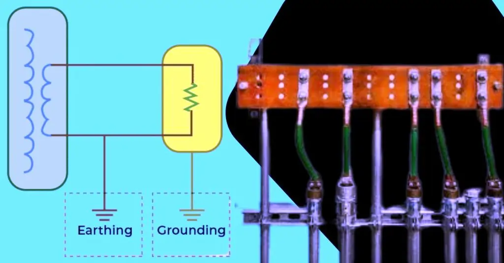
Earthing Grounding
Did you know that inadequate earthing grounding is responsible for nearly 40% of electrical failures? Ensuring a properly grounded system is crucial not only for the safety of your electrical installations but also for their efficiency and longevity. In this post, we will delve into the critical aspects of earthing grounding size calculations, covering essential formulas, materials, and practical applications. By understanding these calculations, you can prevent hazards, comply with regulations, and optimize your electrical systems. Let’s explore how accurate size calculations can enhance the safety and performance of your grounding systems.
Understanding Earthing Grounding
Definition: What is Earthing Grounding?
Earthing grounding, commonly referred to simply as grounding, is the process of connecting the non-current-carrying parts of electrical equipment to the earth. This connection ensures that, in the event of a fault, any excess electricity is safely dissipated into the ground, reducing the risk of electric shock and equipment damage.
Importance: Why Proper Earthing Grounding is Critical
Proper earthing grounding is vital for several reasons:
- Safety: Grounding protects individuals from electric shocks by providing a path for fault currents to flow directly to the earth, preventing them from passing through a person’s body.
- Equipment Protection: It safeguards electrical appliances and machinery from damage due to lightning strikes, power surges, and faults by directing these excess currents safely into the ground.
- Fire Prevention: Proper grounding helps in preventing electrical fires by reducing the risk of faults that could cause overheating or sparking.
- Stable Voltage Levels: Grounding stabilizes voltage levels within an electrical system, providing a reference point for the system voltage and helping to ensure consistent performance.
Basic Principles: Fundamental Concepts Behind Earthing Grounding Systems
Several fundamental concepts are essential to understanding how earthing grounding systems work:
- Grounding Electrode: This is the conductor or a group of conductors used to make a direct connection to the earth. Common grounding electrodes include ground rods, metal water pipes, and building steel.
- Grounding Conductor: This conductor connects the grounding electrode to the electrical system. It must be of sufficient size and conductivity to carry fault currents without overheating.
- Soil Resistivity: The effectiveness of a grounding system heavily depends on the resistivity of the soil. Lower resistivity soils (e.g., clay) provide better grounding than high resistivity soils (e.g., sand or rock).
- Equipotential Bonding: This involves connecting all metallic parts within a system to ensure they are at the same electrical potential, thereby reducing the risk of electric shock.
- Ground Fault: A ground fault occurs when a live conductor touches a grounded part, creating a direct path for current to flow into the earth. Grounding systems are designed to handle such faults safely.
Key Factors Affecting Size Calculations
| Key Factor | Description |
|---|---|
| Soil Resistivity | Influence: Soil resistivity measures how much the soil resists the flow of electric current. Low resistivity soils (e.g., clay, loam, wet soils) are excellent for grounding, while high resistivity soils (e.g., sand, gravel, rocky soils) are less effective. Calculation: Accurate measurement using techniques like the Wenner four-pin method ensures the grounding system can dissipate fault currents effectively. |
| Electrode Material and Size | Materials: Copper: Offers excellent conductivity and corrosion resistance; preferred for most applications. Galvanized Steel: Less conductive but cost-effective; suitable for large installations with budget constraints. Copper-Clad Steel: Combines steel’s strength with copper’s conductivity and corrosion resistance; ideal for durable and efficient applications. Size: Larger electrodes provide more surface area, reducing resistance. Deeper electrodes reach lower resistivity soil layers, enhancing effectiveness. |
| System Design | Single vs. Multiple Electrodes: Single electrodes suffice for small installations, while larger systems often require multiple electrodes in parallel for effective fault current distribution. Grid Design: An interconnected conductor grid for extensive installations reduces resistance and ensures even current distribution. Grounding Rings: Surround structures with grounding rings to protect from lightning and surges. Equipotential Bonding: Ensures all metallic parts are at the same potential, reducing electric shock and equipment damage risks. |
Essential Formulas for Earthing Grounding Calculations
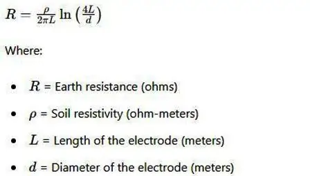
Earth Resistance Calculation:
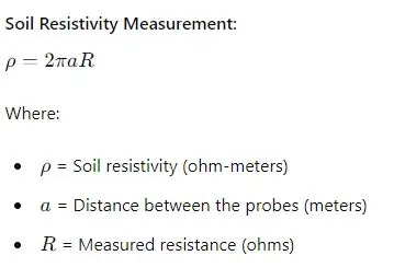
Soil Resistivity Measurement:
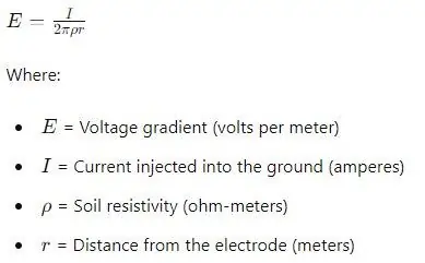
Voltage Gradient Calculation
Step and Touch Voltage Calculations
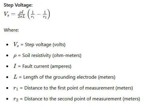
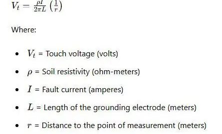
Touch Voltage:
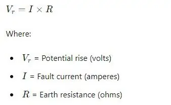
Potential Rise of Grounding System
Grounding Electrode Resistance for Multiple Electrodes:

Earthing Strip Size Calculations
Current Capacity Calculation:
To determine the cross-sectional area of the earthing strip, use the formula:
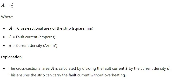
Length and Width Calculation
To calculate the dimensions of the earthing strip, use the following formula:
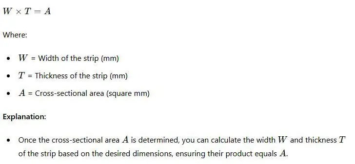
Typical Values
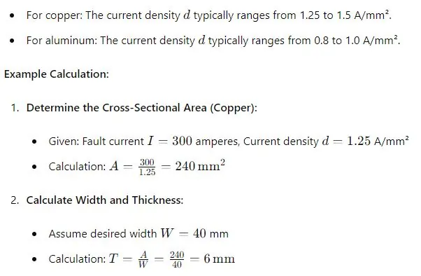
Choosing the Right Electrodes and Strips: Material and Size Selection
- Selecting Electrode Material:
- Copper: Offers excellent conductivity and corrosion resistance. Ideal for most applications.
- Galvanized Steel: Cost-effective with decent conductivity. Suitable for industrial and large-scale systems.
- Copper-Clad Steel: Combines the strength of steel with the conductivity of copper. Ideal for areas with high mechanical stress.
- Stainless Steel: High corrosion resistance but lower conductivity. Best for corrosive environments.
- Selecting Electrode Size:
- Length and Diameter: Larger and longer electrodes reduce resistance. Typical sizes range from 1.2m to 3m in length and 12.5mm to 25mm in diameter.
- Choosing the Right Strips:
- Material: Copper or aluminum strips are commonly used.
- Size: Determined based on current capacity requirements.
Earthing and Grounding Pit Size Calculations
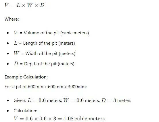
Standard Pit Size:
Typical dimensions: 600mm x 600mm x 3000mm.
Calculation for Pit Volume:
The volume of the pit can be calculated using the formula:
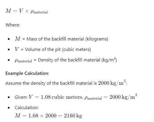
Backfill Material Calculation:
The mass of the backfill material can be calculated using the formula:
Materials Used for Earthing and Grounding
| Material | Properties | Forms | Applications |
|---|---|---|---|
| Copper | Excellent conductivity and corrosion resistance. | Copper rods, strips, plates. | Widely used in all types of earthing systems. |
| Galvanized Steel | Cost-effective with decent conductivity. | Steel rods, strips, plates. | Used in industrial and large-scale earthing systems. |
| Copper-Clad Steel | Combines the strength of steel with the conductivity of copper. | Rods and strips. | Used in areas with high mechanical stress. |
| Stainless Steel | High corrosion resistance, lower conductivity. | Rods and strips. | Used in corrosive environments. |
| Graphite | Stability and resistance to environmental conditions. | Electrodes. | Specialized applications like chemical plants. |
Practical Applications and Case Studies
| Category | Description |
|---|---|
| Residential Installations | Common Scenarios: Grounding electrical panels to ensure safety. Installing grounding rods for home appliances. Ensuring proper grounding for outdoor lighting and security systems.<br>Solutions: Use copper rods due to their excellent conductivity and corrosion resistance. Regularly test soil resistivity and earth resistance to maintain effective grounding. Implement equipotential bonding to ensure all metallic parts are at the same potential. |
| Industrial Applications | Challenges: Handling high fault currents and ensuring safety in large-scale installations. Dealing with varying soil conditions across large industrial sites. Ensuring compliance with stringent industrial standards. Best Practices: Use multiple grounding electrodes connected in parallel to distribute fault currents effectively. Opt for galvanized steel or copper-clad steel for cost-effective yet durable grounding solutions. Regularly inspect and maintain grounding systems to prevent corrosion and ensure long-term effectiveness. |
| Real-Life Examples | Case Study 1: A residential building in a high-resistivity soil area successfully used multiple deep copper electrodes to achieve the required earth resistance. Regular maintenance and testing ensured ongoing compliance and safety. Case Study 2: An industrial plant dealing with high fault currents implemented a grounding grid using galvanized steel rods. Soil resistivity measurements were taken at multiple points to design an effective system. Continuous monitoring and periodic testing ensured the system remained effective over time. |
Tools and Resources for Accurate Calculations
Software Tools: Recommendations for Calculation Software
- ETAP (Electrical Transient Analyzer Program)
- Description: ETAP is a comprehensive software suite used for the design, analysis, and optimization of electrical power systems. It includes modules for grounding system analysis and can handle complex calculations with ease.
- Features: Fault analysis, soil resistivity modeling, grounding grid design, and compliance verification.
- Use Case: Suitable for both residential and industrial applications, providing accurate and detailed grounding system designs.
- SKM Power Tools
- Description: SKM Power Tools offer advanced tools for electrical system analysis, including grounding system design and analysis.
- Features: Ground grid design, step and touch voltage analysis, and soil resistivity calculations.
- Use Case: Ideal for large-scale industrial projects where precise grounding calculations are critical.
- CDEGS (Current Distribution, Electromagnetic Fields, Grounding, and Soil Structure Analysis)
- Description: CDEGS is a specialized software package used for the design and analysis of grounding systems, electromagnetic fields, and soil structure interactions.
- Features: Advanced grounding analysis, soil resistivity modeling, and detailed reporting.
- Use Case: Best suited for complex industrial and utility applications requiring detailed and accurate grounding analysis.
Manual Tools: Traditional Methods and Instruments
- Soil Resistivity Meter
- Description: A device used to measure the resistivity of soil, which is a critical parameter for designing effective grounding systems.
- Features: Accurate resistivity measurements, multiple test methods (e.g., Wenner, Schlumberger), and portability.
- Use Case: Essential for site assessments in both residential and industrial projects.
- Earth Resistance Tester
- Description: An instrument used to measure the resistance of grounding systems, ensuring they meet safety and compliance standards.
- Features: Simple operation, accurate measurements, and suitability for various grounding configurations.
- Use Case: Useful for periodic testing and verification of grounding systems in any setting.
- Clamp-On Ground Resistance Tester
- Description: A tool that allows for non-intrusive measurement of ground resistance without disconnecting the grounding system.
- Features: Easy to use, non-destructive testing, and reliable results.
- Use Case: Ideal for routine maintenance and inspection of grounding systems.
Guidelines and Standards: Key Standards to Follow
- IEEE Standards (Institute of Electrical and Electronics Engineers)
- Key Standards: IEEE Std 80-2013 (Guide for Safety in AC Substation Grounding), IEEE Std 142-2007 (Green Book – Recommended Practice for Grounding of Industrial and Commercial Power Systems).
- Importance: Provides detailed guidelines for designing safe and effective grounding systems, ensuring compliance with industry best practices.
- NEC (National Electrical Code)
- Key Standards: NEC Article 250 (Grounding and Bonding).
- Importance: Specifies the requirements for grounding and bonding in electrical installations in the United States, ensuring safety and compliance with national standards.
- IEC Standards (International Electrotechnical Commission)
- Key Standards: IEC 60364 (Electrical Installations for Buildings), IEC 62305 (Protection Against Lightning).
- Importance: Offers international guidelines for grounding and protection against electrical faults and lightning, ensuring global compliance.
- NFPA (National Fire Protection Association)
- Key Standards: NFPA 70 (National Electrical Code), NFPA 780 (Standard for the Installation of Lightning Protection Systems).
- Importance: Provides safety standards to prevent electrical fires and ensure proper grounding and lightning protection in various installations.
Common Mistakes and How to Avoid Them
Overlooking Soil Resistivity: Consequences and Solutions
Consequences:
- Ineffective Grounding: If soil resistivity is not accurately measured, the grounding system may not effectively dissipate fault currents, leading to potential safety hazards.
- Increased Risk of Electrical Failures: High resistivity soils can prevent proper grounding, increasing the risk of electrical faults and equipment damage.
- Non-compliance: Failure to account for soil resistivity can result in non-compliance with safety standards and regulations.
Solutions:
- Conduct Proper Soil Resistivity Tests: Use methods like the Wenner Four-Pin Method to accurately measure soil resistivity at the site. This involves placing four equally spaced probes in the ground and measuring the resistance between them.
- Regular Monitoring: Periodically retest soil resistivity, especially if there are significant changes in environmental conditions that could affect the soil.
- Adapt Design Based on Results: Use the measured resistivity values to inform the design and placement of grounding electrodes, ensuring they are effective for the specific soil conditions.
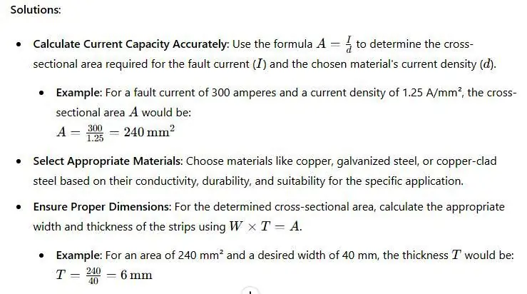
Incorrect Electrode and Strip Sizing: How to Ensure Proper Sizing
Consequences:
Increased Costs: Oversized components can unnecessarily increase costs without providing additional benefits.
Insufficient Current Capacity: Undersized electrodes and strips may not be able to carry the fault currents, leading to overheating and potential failure.
Inefficient Grounding: Incorrect sizing can result in higher resistance paths, reducing the effectiveness of the grounding system.
Neglecting Regular Testing: Importance of Ongoing Maintenance
Consequences:
- Degraded Performance: Without regular testing, degradation of grounding components over time can go unnoticed, leading to reduced effectiveness.
- Safety Hazards: Corrosion, environmental changes, and wear can compromise the grounding system, increasing the risk of electrical shock or fire.
- Regulatory Non-compliance: Failure to maintain and test the grounding system can result in non-compliance with safety standards and regulations.
Solutions:
- Schedule Regular Inspections: Implement a routine inspection schedule to check all grounding components for signs of wear, corrosion, or damage.
- Perform Periodic Testing: Regularly test the earth resistance and continuity of the grounding system using appropriate tools like earth resistance testers and clamp-on ground resistance testers.
- Document and Review Results: Keep detailed records of all tests and inspections, and review them periodically to identify any trends or issues that need addressing.
- Maintain Compliance: Ensure that all maintenance and testing activities comply with relevant standards such as IEEE, NEC, and local regulations.
FAQ on “Earthing Grounding”
Q: What is the primary purpose of earthing grounding?
A: To safely dissipate fault currents into the earth.
Q: How does soil resistivity affect grounding systems?
A: Low resistivity improves efficiency; high resistivity needs special considerations.
Q: Why is regular testing of grounding systems important?
A: Ensures effectiveness and compliance with safety standards
Q: What materials are commonly used for grounding electrodes?
A: Copper, galvanized steel, and copper-clad steel.
Conclusion
Summary
In this comprehensive guide, we’ve covered essential aspects of earthing and grounding systems, focusing on the importance of accurate size calculations. We began by understanding what earthing grounding is and why it is critical for safety and performance. We explored the key factors affecting size calculations, including soil resistivity, electrode material and size, and system design. Practical tools and resources for accurate calculations were highlighted, along with common mistakes and how to avoid them. Practical applications and real-life case studies provided clear context for implementing effective grounding systems.
Call to Action
Now that you have a thorough understanding of the principles and calculations behind effective earthing and grounding systems, it’s time to apply this knowledge. Ensure your systems are properly grounded by conducting accurate soil resistivity tests, selecting the right materials and sizes for electrodes and strips, and performing regular maintenance and testing. Proper grounding not only enhances safety but also ensures compliance with industry standards and prolongs the life of your electrical systems.
Further Reading
To deepen your understanding and stay updated on best practices, consider exploring the following resources:
- IEEE Standards: Detailed guidelines on grounding systems and safety practices.
- National Electrical Code (NEC) Article 250: Comprehensive requirements for grounding and bonding in electrical installations.
- CDEGS Software Documentation: Advanced grounding system analysis and design techniques.
- ETAP and SKM Power Tools: In-depth guides on using these tools for effective grounding system design.
- Calculating Voltage Drop: 5 The Best Tips for Efficiency
