Full Wave Rectifier
Welcome to our comprehensive guide on Full Wave Rectifiers, a vital component in modern electronics and power systems. A full wave rectifier converts alternating current (AC) to direct current (DC), utilizing both halves of the AC waveform for improved efficiency. In this blog post, titled “Full Wave Rectifier: 7 The Most Ultimate Basics & Advantages,” we will delve into the essential concepts and benefits of full wave rectifiers.
You’ll learn about the working principles, key components, and design considerations that make these rectifiers indispensable. We will explore their advantages over half wave rectifiers, practical applications in various electronic devices, and provide troubleshooting and optimization tips. Additionally, we’ll highlight emerging trends and future innovations in rectifier technology. By the end of this post, you’ll have a thorough understanding of full wave rectifiers and their critical role in powering modern electronics.
What is a Full Wave Rectifier?
A Full Wave Rectifier is an electrical device used to convert alternating current (AC) into direct current (DC). Unlike a half wave rectifier, which only uses one half of the AC signal, a full wave rectifier utilizes both halves, making it more efficient and effective.
Definition and Basic Working Principle
A full wave rectifier converts both the positive and negative halves of an AC waveform into a pulsating DC output. This is achieved through the use of diodes, which allow current to flow in only one direction. The result is a smoother and more consistent DC output compared to a half wave rectifier.
Types of Full Wave Rectifiers
There are two main types of full wave rectifiers: Center-Tap and Bridge Rectifiers.
- Center-Tap Full Wave Rectifier:
- Definition: This type uses a center-tapped transformer and two diodes.
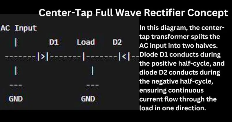
- Working Principle: The center tap of the transformer acts as a reference point, usually connected to ground. During the positive half-cycle of the AC signal, one diode conducts, allowing current to flow through the load. During the negative half-cycle, the other diode conducts, allowing current to flow in the same direction through the load.
- Definition: This type uses four diodes arranged in a bridge configuration.
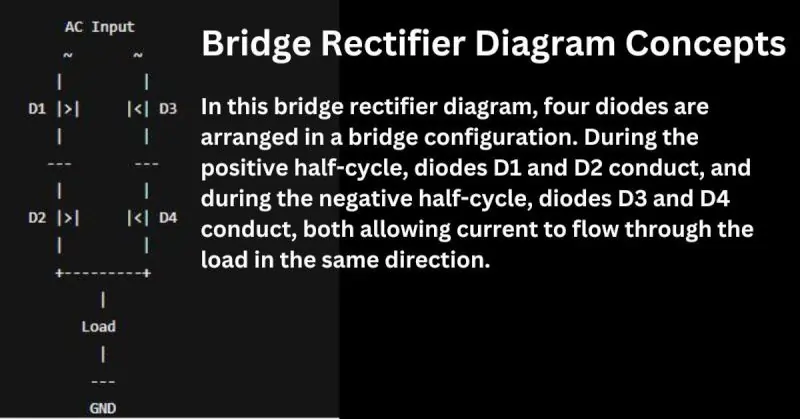
- Working Principle: During the positive half-cycle of the AC input, two of the diodes conduct, allowing current to pass through the load. During the negative half-cycle, the other two diodes conduct, allowing current to flow through the load in the same direction.
Visual Diagrams to Explain Concepts
Center-Tap Full Wave Rectifier Diagram
Bridge Rectifier Diagram:
Detailed Working Principle of Full Wave Rectifiers
Full Wave Rectifiers are essential components in power electronics, converting alternating current (AC) into direct current (DC) efficiently by utilizing both halves of the AC waveform. This section will provide a step-by-step explanation of their working principles, with technical details and comparisons of current flow in the two main types: Center-Tap and Bridge Rectifiers.
Step-by-Step Explanation with Technical Details
Center-Tap Full Wave Rectifier
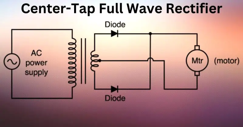
- AC Input: The AC voltage is applied to the primary winding of the center-tapped transformer.
- Transformer Action: The transformer splits the AC voltage into two equal halves with the center tap serving as a reference point.
- Positive Half-Cycle:
- During the positive half-cycle of the AC input, the top end of the transformer secondary winding becomes positive relative to the center tap.
- Diode D1 becomes forward-biased and conducts, allowing current to flow through the load.
- Diode D2 is reverse-biased and does not conduct.
- Negative Half-Cycle:
- During the negative half-cycle of the AC input, the bottom end of the transformer secondary winding becomes positive relative to the center tap.
- Diode D2 becomes forward-biased and conducts, allowing current to flow through the load in the same direction.
- Diode D1 is reverse-biased and does not conduct.
- Output: Both half-cycles of the AC input contribute to the DC output, resulting in a smoother and more continuous DC signal.
Bridge Rectifier
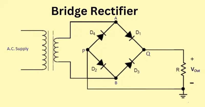
- AC Input: The AC voltage is applied to the input terminals of the bridge rectifier.
- Diode Configuration: Four diodes are arranged in a bridge configuration to direct current flow.
- Positive Half-Cycle:
- During the positive half-cycle, diodes D1 and D2 become forward-biased and conduct.
- Current flows from the positive terminal of the AC source, through D1, the load, D2, and back to the negative terminal of the AC source.
- Diodes D3 and D4 are reverse-biased and do not conduct.
- Negative Half-Cycle:
- During the negative half-cycle, diodes D3 and D4 become forward-biased and conduct.
- Current flows from the positive terminal of the AC source, through D3, the load, D4, and back to the negative terminal of the AC source.
- Diodes D1 and D2 are reverse-biased and do not conduct.
- Output: Both half-cycles of the AC input are converted to DC, providing a continuous and smooth output.
Comparison of Current Flow in Both Types
Center-Tap Full Wave Rectifier:
- Utilizes a center-tapped transformer.
- Requires two diodes.
- Current flows through the load during both half-cycles, but each diode conducts only during one half-cycle.
Bridge Rectifier:
- Does not require a center-tapped transformer.
- Uses four diodes arranged in a bridge configuration.
- Current flows through the load during both half-cycles, with pairs of diodes alternating conduction.
Key Components and Design Considerations for Full Wave Rectifiers
| Component | Description | Design Parameters | Selection Tips |
|---|---|---|---|
| Diodes | Semiconductor devices that allow current to flow in one direction. | Peak Inverse Voltage (PIV) rating should be higher than the maximum AC voltage. Forward current rating must meet or exceed the maximum load current. | Choose diodes with a safety margin in PIV and current ratings. Use fast recovery diodes for high-frequency applications. |
| Transformer | Converts the input AC voltage to a suitable level and provides isolation. | Voltage rating should match the required output voltage. Current rating must support the load requirements. <br> – Center-tap or non-center-tap based on rectifier type. | Select a transformer with sufficient power rating to handle the load without overheating. Ensure good quality insulation and minimal leakage inductance. |
| Capacitor (optional) | Smooths out the pulsating DC output. | Capacitance value depends on the desired ripple voltage and load current. Voltage rating should be higher than the peak output voltage. | Use electrolytic capacitors for higher capacitance values. Consider using a combination of capacitors for better filtering. |
| Resistor (optional) | Used in some designs to control current flow and stabilize voltage. | Resistance value based on circuit requirements. Power rating must handle the dissipated power without overheating. | Choose resistors with a suitable tolerance for accurate performance. Use high wattage resistors for high power applications. |
Design Considerations
- Voltage and Current Requirements:
- Determine the output voltage and current needed for your application.
- Ensure all components can handle these requirements without excessive stress.
- Heat Dissipation:
- Components like diodes and transformers can generate heat during operation.
- Use heat sinks or cooling mechanisms if necessary to prevent overheating.
- Efficiency:
- Higher efficiency reduces power loss and improves performance.
- Select components with low forward voltage drop and high efficiency ratings.
- Ripple Reduction:
- Use capacitors or inductors to smooth out the DC output.
- The choice of filtering components affects the quality of the DC output.
- Safety Margins:
- Always choose components with ratings above the maximum expected values.
- This ensures reliable operation and longevity of the rectifier circuit.
Tips for Choosing the Right Components
- Diodes: Ensure they have a peak inverse voltage (PIV) rating at least 1.5 times the maximum AC voltage and a current rating that matches or exceeds the load current.
- Transformer: Choose one with a voltage rating that matches the desired output voltage and a current rating sufficient for the load. For center-tap designs, ensure it has a center tap.
- Capacitors: Select capacitors with appropriate voltage ratings and sufficient capacitance to reduce ripple effectively. Electrolytic capacitors are common for higher capacitance needs.
- Resistors: Use resistors with accurate resistance values and appropriate power ratings to handle the expected power dissipation without overheating.
Advantages of Full Wave Rectifiers
Full Wave Rectifiers are widely used in electronic circuits due to their numerous advantages over half-wave rectifiers. Here are the key benefits:
Higher Efficiency Compared to Half-Wave Rectifiers
Full wave rectifiers utilize both halves of the AC input waveform, resulting in higher efficiency. In contrast, half-wave rectifiers only use one half of the input signal, leading to wasted energy.
| Feature | Full Wave Rectifier | Half Wave Rectifier |
|---|---|---|
| Utilization of AC Signal | Both positive and negative halves | Only positive or negative half |
| Energy Efficiency | Higher | Lower |
| Power Delivery | Continuous | Intermittent |
Lower Ripple Factor and Smoother DC Output
The ripple factor, which measures the smoothness of the DC output, is significantly lower in full wave rectifiers. This results in a more stable and consistent DC signal, which is crucial for sensitive electronic devices.
| Parameter | Full Wave Rectifier | Half Wave Rectifier |
|---|---|---|
| Ripple Factor | Lower | Higher |
| Output Smoothness | Smoother | Less smooth |
| Need for Filtering | Less | More |
Better Transformer Utilization and Load Regulation
Full wave rectifiers make better use of the transformer, especially in the bridge rectifier configuration where no center-tap is required. This improves load regulation and allows for more efficient power transfer.
| Aspect | Full Wave Rectifier | Half Wave Rectifier |
|---|---|---|
| Transformer Utilization | Full | Partial |
| Load Regulation | Better | Inferior |
| Component Stress | Lower | Higher |
Detailed Advantages
- Higher Efficiency:
- Explanation: By using both halves of the AC waveform, full wave rectifiers convert more of the input power into usable DC power.
- Impact: This results in less energy loss and more efficient operation of the electronic circuit.
- Lower Ripple Factor:
- Explanation: The ripple factor is a measure of the residual AC component in the output. Full wave rectifiers produce a lower ripple factor because the output is smoother and closer to pure DC.
- Impact: This reduces the need for extensive filtering and provides a more stable DC supply, which is essential for powering sensitive electronic components.
- Better Transformer Utilization:
- Explanation: In a center-tap full wave rectifier, the transformer is used more effectively because it conducts during both halves of the AC cycle. In a bridge rectifier, the transformer is even more efficiently used as it does not require a center tap.
- Impact: This leads to improved load regulation, meaning the output voltage remains more consistent under varying load conditions. Additionally, it reduces the stress on the transformer and other components, enhancing the overall reliability and longevity of the power supply.
Practical Applications of Full Wave Rectifiers in Modern Electronics
Full Wave Rectifiers are critical components in various electronic systems, providing efficient and reliable conversion of AC to DC power. Here are some key applications in modern electronics:
Power Supplies for Consumer Electronics
Full wave rectifiers are widely used in power supplies for consumer electronics such as televisions, radios, computers, and mobile chargers. They ensure a stable and smooth DC output, which is essential for the proper functioning of these devices.
| Device | Role of Full Wave Rectifier | Benefit |
|---|---|---|
| Televisions | Converts AC mains to stable DC for internal circuits | Clearer picture and sound |
| Radios | Provides consistent DC voltage for sensitive components | Improved reception and clarity |
| Computers | Ensures reliable power for CPU, memory, and peripherals | Prevents crashes and data loss |
| Mobile Chargers | Efficiently charges batteries with a steady DC output | Faster and safer charging |
Battery Charging Circuits
Full wave rectifiers are essential in battery charging circuits for both consumer and industrial applications. They provide a continuous and smooth DC voltage, which is necessary for safe and efficient battery charging.
| Application | Role of Full Wave Rectifier | Benefit |
|---|---|---|
| Smartphone Chargers | Converts AC to DC to charge lithium-ion batteries | Prolongs battery life |
| Electric Vehicles | Charges large battery packs efficiently and reliably | Extends range and battery life |
| Portable Devices | Powers charging circuits in devices like power banks | Reliable and rapid charging |
Use in Renewable Energy Systems and Electric Vehicles
Full wave rectifiers are crucial in renewable energy systems and electric vehicles, where they convert the variable AC output from generators and alternators into a stable DC voltage for storage or direct use.
| System | Role of Full Wave Rectifier | Benefit |
|---|---|---|
| Solar Power Systems | Converts AC from inverters to stable DC for storage | Maximizes energy storage efficiency |
| Wind Turbines | Rectifies AC from generators to charge batteries | Provides consistent power output |
| Electric Vehicles (EVs) | Charges the vehicle’s battery pack from regenerative braking | Increases driving range and efficiency |
Real-World Case Studies and Examples
- Case Study: Power Supply in Personal Computers:
- Context: Modern personal computers require a stable and reliable DC power supply to operate efficiently.
- Implementation: Full wave rectifiers are used in the power supply units (PSUs) of computers to convert AC mains into smooth DC voltage.
- Outcome: The use of full wave rectifiers ensures that all components receive the necessary power, reducing the risk of malfunctions and enhancing the overall performance of the computer.
- Case Study: Solar Energy Storage Systems:
- Context: Solar power systems need to store energy efficiently in batteries to provide a continuous power supply.
- Implementation: Full wave rectifiers are used to convert the AC output of solar inverters into a stable DC voltage for battery charging.
- Outcome: This allows for maximum energy storage efficiency, ensuring that the solar power system can provide reliable power even when sunlight is not available.
- Example: Electric Vehicle (EV) Charging Stations:
- Context: EV charging stations require efficient rectification to charge vehicle batteries quickly and safely.
- Implementation: Full wave rectifiers are incorporated into EV charging stations to convert AC from the grid into DC for battery charging.
- Outcome: This results in faster charging times and better energy efficiency, contributing to the widespread adoption of electric vehicles.
Troubleshooting and Optimization Tips for Full Wave Rectifiers
Full wave rectifiers are reliable components, but like all electronic devices, they can encounter issues. Here are some common problems, practical solutions, and advanced optimization tips to ensure your full wave rectifier operates efficiently.
Common Issues and How to Diagnose Them
| Issue | Symptoms | Diagnosis |
|---|---|---|
| Diode Failure | No output voltage, fluctuating output | Check diodes with a multimeter; look for open or short circuits |
| Transformer Issues | Overheating, unusual noises, no output | Measure transformer secondary voltage; check for winding damage |
| Excessive Ripple | High ripple voltage in the output | Measure ripple with an oscilloscope; check filter capacitors |
| Poor Regulation | Output voltage drops under load | Measure voltage drop; check transformer and diode ratings |
Practical Solutions and Best Practices
| Issue | Solution | Best Practices |
|---|---|---|
| Diode Failure | Replace faulty diodes with ones of suitable ratings | Use diodes with a safety margin in voltage and current ratings |
| Transformer Issues | Replace or rewind transformer if damaged | Use transformers with proper insulation and power ratings |
| Excessive Ripple | Add or replace filter capacitors | Use high-quality capacitors; consider using multiple capacitors |
| Poor Regulation | Use a voltage regulator circuit to stabilize output | Ensure transformer and diodes are not operating at their limits |
Summary of Troubleshooting and Optimization
| Aspect | Common Issues | Solutions | Advanced Tips |
|---|---|---|---|
| Diodes | Failure, overheating | Replace with suitable rated diodes | Use Schottky diodes, implement snubber circuits |
| Transformer | Overheating, no output | Replace or rewind damaged transformer | Ensure proper insulation and use appropriate ratings |
| Ripple | Excessive ripple voltage | Add or replace filter capacitors | Use a combination of electrolytic and ceramic capacitors |
| Regulation | Voltage drops under load | Use voltage regulator circuits | Implement active rectification |
| Heat Management | Overheating components | Use heat sinks or cooling fans | Enhance cooling mechanisms |
| Grounding | Noise, EMI | Ensure solid grounding | Proper grounding techniques to reduce interference |
Future Trends and Innovations in Full Wave Rectifiers
Full wave rectifiers are continually evolving to meet the demands of modern technology. Here’s a detailed look at the future trends and innovations in this field:
Emerging Technologies Utilizing Full Wave Rectifiers
Full wave rectifiers are finding new applications in cutting-edge technologies, driven by the need for efficient and reliable power conversion.
- Internet of Things (IoT) Devices:
- Context: IoT devices require efficient power management to operate reliably over extended periods.
- Application: Full wave rectifiers are used in power supply circuits to ensure stable DC output for sensors and communication modules.
- Impact: Enhances the performance and longevity of IoT devices.
- Wearable Electronics:
- Context: Wearable devices such as smartwatches and fitness trackers need compact and efficient power solutions.
- Application: Miniaturized full wave rectifiers provide the necessary DC power from small AC sources or inductive chargers.
- Impact: Improves battery life and device reliability.
- Renewable Energy Systems:
- Context: The integration of renewable energy sources like solar and wind power into the grid requires efficient power conversion.
- Application: Full wave rectifiers convert AC output from inverters to DC for storage in batteries or direct use.
- Impact: Maximizes energy efficiency and stability in renewable energy systems.
Innovations in Design and Materials
Advancements in design and materials are enhancing the performance and efficiency of full wave rectifiers.
- Silicon Carbide (SiC) and Gallium Nitride (GaN) Diodes:
- Description: SiC and GaN diodes offer lower forward voltage drop and higher efficiency compared to traditional silicon diodes.
- Benefits: Improved thermal performance and higher switching speeds, making them ideal for high-frequency applications.
- Integrated Rectifier Modules:
- Description: These modules combine multiple rectifier components into a single, compact package.
- Benefits: Simplifies circuit design, reduces space, and improves reliability by minimizing interconnections.
- Advanced Cooling Techniques:
- Description: Innovations in cooling, such as micro-channel heat sinks and advanced thermal interface materials.
- Benefits: Enhance heat dissipation, allowing rectifiers to operate at higher power levels without overheating.
Predictions for the Future of Rectifier Technology
The future of full wave rectifiers looks promising with several exciting developments on the horizon.
- Integration with Smart Grids:
- Prediction: Full wave rectifiers will play a crucial role in smart grid technologies, enabling more efficient power distribution and management.
- Impact: Improved grid stability and energy efficiency, supporting the growth of renewable energy sources.
- Advances in Power Density:
- Prediction: Continued miniaturization and integration will lead to rectifiers with higher power densities.
- Impact: Smaller, more powerful rectifiers suitable for compact and portable electronic devices.
- Enhanced Energy Harvesting:
- Prediction: Full wave rectifiers will be integral to advanced energy harvesting systems, capturing energy from various sources like ambient RF, vibrations, and thermal gradients.
- Impact: Supports the development of self-sustaining, battery-less electronic devices.
- AI and Machine Learning Integration:
- Prediction: The integration of AI and machine learning in power management systems will optimize the performance and efficiency of full wave rectifiers in real-time.
- Impact: Adaptive rectifier systems that dynamically adjust to changing load conditions, maximizing efficiency and reliability.
FAQ on “Full Wave Rectifier”
Q: What is a full wave rectifier?
A: A full wave rectifier converts both halves of an AC signal into a continuous DC output.
Q: What are the types of full wave rectifiers?
A: The two main types are center-tap rectifiers and bridge rectifiers.
Q: Why is a full wave rectifier more efficient than a half wave rectifier?
A: It utilizes both halves of the AC waveform, resulting in higher efficiency and smoother DC output.
Q: What are common applications of full wave rectifiers?
A: They are used in power supplies, battery charging circuits, and renewable energy systems.
Conclusion
Full wave rectifiers are indispensable components in modern electronics, offering higher efficiency, smoother DC output, and better transformer utilization compared to half wave rectifiers. Their applications span across consumer electronics, battery charging circuits, and renewable energy systems, ensuring reliable and stable power supply. By understanding their working principles, troubleshooting common issues, and implementing optimization tips, you can effectively enhance the performance of your electronic circuits. Whether you’re designing power supplies or integrating renewable energy solutions, full wave rectifiers provide the foundation for efficient and dependable power conversion.
