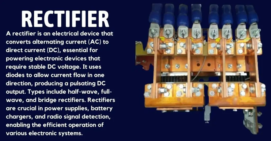
Rectifier Secrets
Rectifiers play a crucial role in modern electronics, transforming alternating current (AC) into direct current (DC). This conversion is essential because most electronic devices and power supplies require a stable DC voltage to function correctly. Whether you’re powering your smartphone, laptop, or any other electronic device, a rectifier is at work behind the scenes.
In this post, we delve into the five most useful methods of rectification, exploring their unique advantages and applications. From half-wave to full-wave rectification, bridge rectifiers, filters, and voltage regulation techniques, we will uncover the secrets behind these critical components. Understanding these methods not only enhances your knowledge but also equips you to make informed decisions for your electronic projects and power supply needs. Join us as we explore the fascinating world of rectifiers and their indispensable role in modern technology.
What is a Rectifier & Its Uses?
What is a Rectifier?
A rectifier is an electrical device that converts alternating current (AC), which periodically reverses direction, into direct current (DC), which flows in a single direction. Rectifiers use diodes to allow current flow during only one half of the AC cycle, effectively transforming AC into DC. They are essential in converting the AC power supplied by power grids into DC power that can be used by various electronic devices and equipment.
Uses of Rectifiers
Rectifiers are widely used in various applications, including:
- Power Supply Circuits: Rectifiers convert the AC from the power grid into DC, which is needed for powering electronic devices like computers, televisions, and chargers.
- Battery Charging: In battery chargers, rectifiers are used to convert AC into DC, allowing batteries to be recharged efficiently.
- Welding Equipment: Rectifiers are used in welding machines to convert AC into DC, which provides a steady and controlled current for welding operations.
- Radio Signal Demodulation: In radio and communication systems, rectifiers help demodulate signals by converting the high-frequency AC signal into DC.
Essential Formulas for Designing Efficient Rectifier Circuits
Understanding these key formulas will help you design and analyze rectifier circuits effectively. Each formula serves a specific purpose in evaluating and optimizing the performance of rectifiers.
1. Full-Wave Rectifier Output Voltage
To calculate the average DC output voltage of a full-wave rectifier, use the following formula:
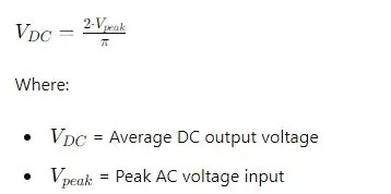
This formula helps in determining the expected DC output from your full-wave rectifier circuit.
2. Peak Inverse Voltage (PIV) for Diodes in a Rectifier
It is crucial to know the maximum reverse voltage a diode can handle without breaking down. This is given by:
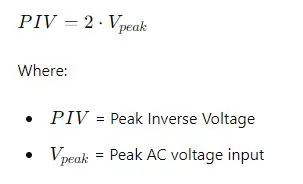
Ensuring your diodes can withstand the PIV is vital for the reliability of your rectifier circuit.
3. RMS Voltage for Full-Wave Rectifier
To find the effective value of the fluctuating DC voltage, calculate the RMS voltage using:
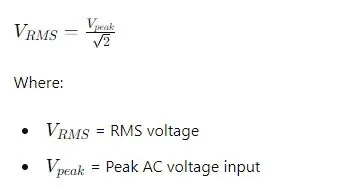
This value is important for assessing the overall power of the output signal.
4. Average DC Output Voltage for Half-Wave Rectifier
For a half-wave rectifier, the average DC output voltage can be found with:
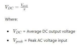
This formula helps in understanding the efficiency and output characteristics of half-wave rectifiers.
5. Ripple Factor for Full-Wave Rectifier
The ripple factor indicates the amount of AC ripple present in the DC output. It is calculated as:
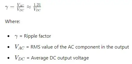
A lower ripple factor signifies a smoother DC output, which is desirable for most applications.
6. Load Current for a Rectifier
To calculate the load current, given the load resistance and average DC output voltage, use:
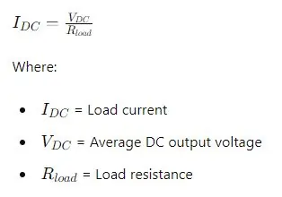
Knowing the load current is essential for ensuring that the rectifier can supply sufficient current to the load without exceeding its capacity.
Half-Wave Rectification
Overview
Half-wave rectification is a process used to convert alternating current (AC) to direct current (DC). In this method, only one half of the AC waveform (either the positive or negative half) is allowed to pass through, while the other half is blocked. This results in a pulsating DC output that is not continuous but still serves various practical purposes. The basic working principle involves using a single diode to achieve this rectification.
How It Works
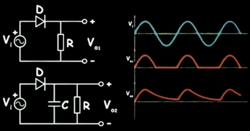
In half-wave rectification, the AC input signal is applied to a circuit containing a single diode and a load resistor. Here’s a step-by-step explanation of the process:
- Positive Half-Cycle: During the positive half-cycle of the AC input, the diode becomes forward-biased (conductive), allowing current to pass through it. The current flows through the load resistor, creating a positive voltage across it.
- Negative Half-Cycle: During the negative half-cycle, the diode becomes reverse-biased (non-conductive), blocking the current flow. As a result, no current flows through the load resistor, and the output voltage is zero during this period.
- Output Waveform: The output is a series of positive pulses corresponding to the positive half-cycles of the AC input. This produces a pulsating DC voltage with a frequency equal to the input AC frequency.
Below is a simple diagram showing the basic setup and waveforms:
Advantages and Disadvantages
Advantages:
- Simplicity: The circuit design is straightforward, requiring only one diode and a few passive components.
- Cost-Effective: Fewer components mean lower cost and easier implementation.
- Low Component Stress: Only one diode is involved, reducing the stress on individual components.
Disadvantages:
- Inefficiency: Since only half of the input AC signal is used, the efficiency is relatively low.
- Pulsating DC Output: The output is not a smooth DC voltage but a series of pulses, which may require additional filtering for certain applications.
- High Ripple: The high ripple factor can affect the performance of sensitive electronic circuits.
Applications
Half-wave rectifiers are used in various practical applications, often where the simplicity and cost-effectiveness outweigh the disadvantages:
- Signal Demodulation: Used in radio receivers to extract the audio signal from the modulated carrier wave.
- Battery Chargers: Simple battery chargers for small batteries where a smooth DC is not critical.
- Power Supplies for Low-Power Devices: Suitable for devices that do not require a perfectly smooth DC voltage, such as LED drivers or small household appliances.
Full-Wave Rectification
Overview
Full-wave rectification is a method used to convert alternating current (AC) to direct current (DC) more efficiently than half-wave rectification. Unlike half-wave rectification, which uses only one half of the AC cycle, full-wave rectification utilizes both halves, resulting in a smoother and more continuous DC output. This method is preferred in applications requiring higher efficiency and lower ripple in the DC supply.
Types of Full-Wave Rectifiers
- Center-Tapped Full-Wave Rectifier:
- Uses a center-tapped transformer and two diodes.
- Each half of the transformer secondary winding conducts current during alternate half-cycles of the input AC signal.
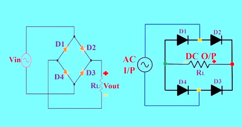
- Bridge Full-Wave Rectifier:
- Uses four diodes arranged in a bridge configuration.
- Does not require a center-tapped transformer, making it more versatile and easier to implement in many circuits.
How It Works
Center-Tapped Full-Wave Rectifier:
- Positive Half-Cycle: During the positive half-cycle of the AC input, the diode connected to the positive side of the transformer secondary winding becomes forward-biased and conducts current. The other diode is reverse-biased and does not conduct. The current flows through the load resistor, creating a positive voltage across it.
- Negative Half-Cycle: During the negative half-cycle, the roles of the diodes are reversed. The diode previously reverse-biased now becomes forward-biased and conducts, while the other diode becomes reverse-biased. This results in current flow through the load resistor in the same direction as during the positive half-cycle.
Bridge Full-Wave Rectifier:
- Positive Half-Cycle: During the positive half-cycle of the AC input, two diodes (D1 and D2) become forward-biased and conduct current, while the other two diodes (D3 and D4) are reverse-biased. The current flows through the load resistor, producing a positive voltage.
- Negative Half-Cycle: During the negative half-cycle, the roles of the diodes reverse. Diodes D3 and D4 become forward-biased and conduct current, while D1 and D2 are reverse-biased. The current continues to flow through the load resistor in the same direction, maintaining a continuous DC output.
Below are diagrams showing the basic setup and waveforms for each type:
Center-Tapped Full-Wave Rectifier Diagram:
Bridge Full-Wave Rectifier Diagram:
Advantages and Disadvantages
Advantages:
- Higher Efficiency: Utilizes both halves of the AC cycle, leading to better efficiency and higher average output voltage.
- Lower Ripple: Produces a smoother DC output with lower ripple compared to half-wave rectification.
- Continuous DC Output: Provides a more stable and continuous DC supply, which is essential for many electronic applications.
Disadvantages:
- Complexity: Requires more components (diodes and transformers) than half-wave rectifiers.
- Cost: Slightly higher cost due to additional components.
- Transformer Use: Center-tapped rectifiers require a special transformer, which can increase design complexity and cost.
Applications
Full-wave rectifiers are widely used in various applications where efficient and smooth DC voltage is crucial:
- Power Supplies: Essential in AC to DC power supplies for electronic devices, ensuring stable DC output for components like microprocessors, sensors, and other digital electronics.
- Battery Charging: Used in battery chargers to provide consistent and efficient charging currents.
- Audio Equipment: Employed in audio amplifiers and other audio equipment where a stable DC supply is necessary for optimal performance.
- Industrial Controls: Utilized in industrial control systems to convert AC to DC for motor drives and other control equipment.
Bridge Rectification
Overview
Bridge rectification is a highly efficient method of converting alternating current (AC) to direct current (DC) using a specific configuration of four diodes. Unlike other rectification methods, bridge rectification does not require a center-tapped transformer, making it versatile and easier to implement in various circuits. This unique configuration allows the full use of both halves of the AC cycle, resulting in a smooth and continuous DC output.
How It Works
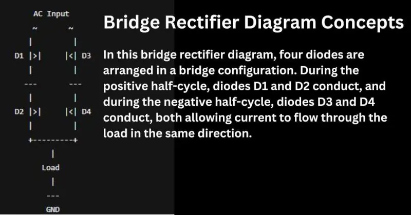
The bridge rectifier circuit consists of four diodes (D1, D2, D3, and D4) arranged in a bridge configuration. The AC input is applied to two opposite corners of the bridge, while the DC output is taken from the remaining two corners.
Positive Half-Cycle:
- During the positive half-cycle of the AC input, diodes D1 and D2 become forward-biased (conducting), while diodes D3 and D4 are reverse-biased (non-conducting).
- Current flows from the positive AC input through D1, across the load resistor (R), and returns through D2 to the negative AC input.
- This creates a positive voltage across the load resistor.
Negative Half-Cycle:
- During the negative half-cycle, diodes D3 and D4 become forward-biased, while diodes D1 and D2 are reverse-biased.
- Current flows from the negative AC input through D3, across the load resistor in the same direction as during the positive half-cycle, and returns through D4 to the positive AC input.
- This ensures that the current through the load resistor always flows in the same direction, maintaining a continuous DC output.
Below is a diagram showing the bridge rectifier configuration and waveforms:
Advantages and Disadvantages
Advantages:
- No Need for Center-Tapped Transformer: Simplifies the design and reduces cost.
- High Efficiency: Utilizes both halves of the AC cycle, providing better efficiency and higher average output voltage.
- Smooth DC Output: Produces a continuous DC output with lower ripple, suitable for many electronic applications.
- Versatility: Can be used with any transformer or directly with the AC mains.
Disadvantages:
- Complexity: Requires four diodes instead of one or two, increasing circuit complexity.
- Voltage Drop: The voltage drop is higher (two diode drops per half-cycle) compared to other rectifiers, which can affect efficiency slightly.
Applications
Bridge rectifiers are widely used in various applications where efficient and smooth DC voltage is essential:
- Power Supplies: Integral to AC to DC power supplies for electronic devices, providing stable DC output for components like microprocessors and sensors.
- Battery Charging: Used in battery chargers to deliver consistent and efficient charging currents.
- Industrial Equipment: Employed in industrial control systems to convert AC to DC for motor drives and other control equipment.
- Consumer Electronics: Found in a variety of consumer electronics, including televisions, radios, and audio equipment, where a stable DC supply is necessary for optimal performance.
Using Filters with Rectifiers
Overview
Filters play a crucial role in rectifier circuits by improving the quality of the DC output. After rectification, the output voltage contains ripples due to the alternating nature of the input AC signal. Filters smooth out these ripples, resulting in a more stable and continuous DC voltage. This is essential for the proper functioning of many electronic devices, which require a steady DC supply to operate efficiently and reliably.
Types of Filters
- Capacitor Filters
- Inductor Filters
- LC Filters (Combination of Inductor and Capacitor)
How They Work
Capacitor Filters:
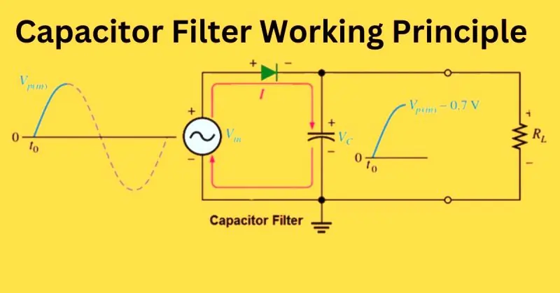
- Working Principle: A capacitor is connected in parallel with the load resistor across the output of the rectifier. During the positive half-cycle, the capacitor charges to the peak voltage of the rectified output. During the negative half-cycle, when the output voltage drops, the capacitor discharges slowly, providing current to the load and smoothing the voltage.
- Effectiveness: The larger the capacitance, the better the smoothing effect, as it can store more charge and release it during the voltage dips.
Inductor Filters:
- Working Principle: An inductor is connected in series with the load resistor. Inductors resist changes in current due to their property of inductance. When the rectified output current increases, the inductor opposes the increase, smoothing the current flow. Similarly, when the current decreases, the inductor releases stored energy to maintain a steady current.
- Effectiveness: Inductors are particularly effective at filtering high-frequency ripples, but they can be bulky and expensive compared to capacitors.
LC Filters:
- Working Principle: An LC filter combines the advantages of both inductors and capacitors. An inductor is placed in series with the load, and a capacitor is placed in parallel with the load. The inductor smooths out the current, while the capacitor smooths out the voltage. This combination provides superior filtering, significantly reducing both high and low-frequency ripples.
- Effectiveness: LC filters offer the best performance in terms of ripple reduction and voltage smoothing but can be more complex and costly to implement.
Advantages and Disadvantages
Advantages:
- Improved DC Quality: Filters significantly reduce voltage ripples, providing a smooth and stable DC output.
- Enhanced Performance: Electronic devices perform better and more reliably with a stable DC supply.
- Versatility: Different types of filters can be used based on specific requirements and applications.
Disadvantages:
- Increased Cost: Adding filters, especially LC filters, can increase the overall cost of the circuit.
- Complexity: Incorporating filters into rectifier circuits can make the design more complex.
- Size and Weight: Inductors, in particular, can be bulky and heavy, which may not be suitable for compact or portable applications.
Applications
Filters are widely used in various applications to ensure the quality of the DC output from rectifier circuits:
- Power Supplies: Essential in power supply units for computers, televisions, and other electronic devices to provide a stable DC output.
- Audio Equipment: Used in audio amplifiers and other audio equipment to reduce noise and ensure a clean audio signal.
- Battery Chargers: Employed in battery chargers to provide a consistent and smooth charging current, enhancing battery life and performance.
- Industrial Equipment: Used in industrial control systems and motor drives to ensure reliable operation by providing a stable DC supply.
Voltage Regulation Techniques
Overview
Voltage regulation is crucial in rectifier circuits to ensure a stable and consistent DC output, despite variations in input voltage or load conditions. This stability is essential for the reliable operation of electronic devices, which require precise voltage levels to function correctly. Without proper voltage regulation, fluctuations can cause performance issues or damage sensitive components.
Techniques
- Zener Diodes
- Linear Voltage Regulators
- Switching Voltage Regulators
How They Work
Zener Diodes:
- Working Principle: Zener diodes are designed to operate in reverse breakdown mode. When the voltage across the Zener diode exceeds its breakdown voltage, it maintains a constant voltage across it. By placing a Zener diode in parallel with the load, it can regulate the output voltage by shunting excess current and maintaining a steady voltage.
- Integration with Rectifiers: Typically used with a series resistor to drop the excess voltage, the Zener diode ensures that the load receives a stable voltage.
Linear Voltage Regulators:
- Working Principle: Linear regulators use a feedback mechanism to maintain a constant output voltage. They consist of a pass transistor (controlled by an error amplifier) that adjusts the resistance to keep the output voltage steady. Common types include the 78xx series for positive voltages and 79xx series for negative voltages.
- Integration with Rectifiers: Placed after the rectifier and filter stages, linear regulators provide a smooth and stable DC output, regardless of input voltage variations (within specified limits).
Switching Voltage Regulators:
- Working Principle: Switching regulators use high-frequency switching and inductive or capacitive storage elements to convert and regulate voltage. They are more efficient than linear regulators and can step up (boost), step down (buck), or invert voltages. Types include buck, boost, and buck-boost converters.
- Integration with Rectifiers: Switching regulators are used after rectification and initial filtering to provide efficient voltage regulation, especially in applications requiring high efficiency and low heat dissipation.
Advantages and Disadvantages
Zener Diodes:
- Advantages: Simple, cost-effective, and easy to implement for low-current applications.
- Disadvantages: Limited current handling capacity, less efficient for high-power applications, and can produce significant heat.
Linear Voltage Regulators:
- Advantages: Provides excellent voltage stability and low noise, simple design, and easy to use.
- Disadvantages: Low efficiency, especially when the difference between input and output voltage is high, leading to significant heat generation and power loss.
Switching Voltage Regulators:
- Advantages: High efficiency, capable of handling large current loads, can step up, step down, or invert voltages, and produce less heat.
- Disadvantages: More complex design, can generate electromagnetic interference (EMI) due to high-frequency switching, and typically more expensive than linear regulators.
Applications
Zener Diodes:
- Voltage Reference: Used as a voltage reference in various circuits.
- Simple Regulators: Suitable for low-power applications such as signal conditioning and small power supplies.
Linear Voltage Regulators:
- Power Supplies: Widely used in linear power supplies for stable voltage outputs in electronic devices like computers, televisions, and audio equipment.
- Battery Chargers: Employed in battery chargers to provide a consistent charging voltage.
Switching Voltage Regulators:
- DC-DC Converters: Common in portable electronics like smartphones, tablets, and laptops, where high efficiency is crucial.
- Industrial Power Supplies: Used in industrial control systems and motor drives for efficient voltage regulation.
- Renewable Energy Systems: Integrated into solar power systems and wind turbines to regulate and optimize the power output.
AQ on “Rectifier”
Q: What is the primary function of a rectifier?
A: A rectifier converts alternating current (AC) to direct current (DC).
Q: What are the common types of rectifiers?
A: Common types include half-wave, full-wave, and bridge rectifiers.
Q: Why are bridge rectifiers preferred in many applications?
A: Bridge rectifiers provide higher efficiency and do not require a center-tapped transformer.
Q: What is the role of filters in rectifier circuits?
A: Filters smooth out the ripples in the DC output to provide a stable voltage.
Conclusion
Rectifiers are essential components in modern electronic systems, transforming AC to DC to ensure a stable and reliable power supply. By understanding the various rectification methods—half-wave, full-wave, and bridge rectifiers—along with the importance of filtering and voltage regulation, one can design more efficient and effective circuits. Whether you’re powering a simple device or a complex industrial system, selecting the right rectification and regulation techniques is crucial for optimal performance. With this knowledge, you can ensure your electronic applications run smoothly and efficiently, enhancing both functionality and longevity.
