Rotors Mastery
Rotors are the heart of marine generators, transforming mechanical energy into the electrical power that keeps ships running smoothly. This blog post aims to demystify the top five functions of rotors in marine generators, providing you with essential knowledge to enhance your understanding and maintenance of these critical components. By exploring these functions, you’ll gain insights into how rotors contribute to the overall efficiency, stability, and performance of marine generators. Understanding these roles is vital, as it enables better maintenance practices, troubleshooting, and optimization of your marine power systems, ensuring reliability and longevity at sea. Dive into the mechanics behind these indispensable parts and discover how mastering rotor functions can revolutionize your marine operations.
Overview of Marine Generators
Definition and Components
Marine generators are essential power systems used on ships and marine vessels to convert mechanical energy into electrical energy. These generators ensure the availability of electricity for various onboard systems, from navigation and communication equipment to lighting and auxiliary machinery. The primary components of marine generators include:
- Engine: Provides the mechanical energy required for the generator.
- Alternator: Converts mechanical energy into electrical energy.
- Rotor: A crucial part of the alternator that interacts with the stator to generate electricity.
- Stator: Works with the rotor to produce the electrical output.
- Cooling System: Maintains the generator’s temperature to prevent overheating.
- Control System: Manages the generator’s operation and output.
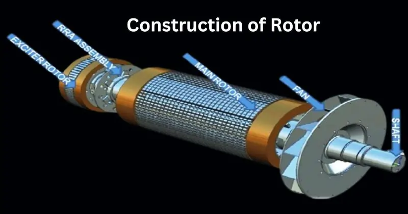
Construction of Rotor

A Rotor in marine generators consists of the following assemblies:
- Shaft
- Rotor Core Assembly
- Field Winding
- Fan
- Excitation System
Shaft
The shaft is made of forged steel, with an extension used to mount the coupling or an integral flanged extension provided as per customer requirements. This facilitates torque transmission during normal operating, overload, and short circuit conditions.
Rotor Core Assembly
Low-loss laminated steel sheets form the field core. Duct pieces are welded at suitable lengths in its axial direction, creating ventilating ducts for effective interior cooling. The outer surface of the field core includes a damper winding to help operate with unbalanced loads.
Field Winding
The field winding is configured according to the rotor slot and design requirements. It undergoes vacuum pressure impregnation for high mechanical and electrical strength. Overhang banding and steel rings are used in high-speed, high-megawatt applications, ensuring durability at critical speeds. The rotor is manufactured and inspected with meticulous attention to part machining, assembly, and balancing.
Fan
Fans are assembled on the shaft to facilitate air circulation. These components are made from rolled-steel plates, welded, stress-relieved, and heaved for optimal performance.
Excitation System
The excitation system includes the construction of the exciter stator, exciter rotor, and rotating rectifier assembly (RRA).
I. Exciter Stator Construction
The exciter stator core is made from high-quality laminated silicon steel sheets. The stator is wire wound, varnish impregnated, and pressed into the exciter frame. It houses the field winding that supplies flux to the exciter rotor. DC supply is fed to the exciter stator from the AVR.
II. Exciter Rotor Construction
The exciter rotor core is mounted on the main shaft or extended shaft, tightened and fitted with suitable torque, and locked. Coils insulated with Nomex are wound on the exciter rotor and varnish impregnated. The output is converted into DC in the rotating rectifier assembly and fed to the main field.
III. Rotating Rectifier Assembly (RRA)
A three-phase full-wave bridge rectifier converts AC output from the exciter rotor to DC, which is fed into the main field. The RRA includes six or twelve diodes (depending on design requirements) fixed to aluminum heat sinks. These heat sinks are mounted on an insulating plate, attached to the exciter rotor core clamp through a fitting stand.
Function 1: Electromagnetic Induction
Explanation: Detailed Description of Electromagnetic Induction
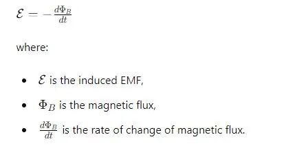
Electromagnetic induction is the process by which a changing magnetic field within a conductor induces an electrical current. This principle was discovered by Michael Faraday in 1831 and forms the foundation of modern electrical generation. According to Faraday’s Law of Induction, the induced electromotive force (EMF) in a closed circuit is proportional to the rate of change of the magnetic flux through the circuit. Mathematically, this is expressed as:

Rotor’s Role: How the Rotor Contributes to Generating Electricity
In marine generators, the rotor is the rotating component that creates a moving magnetic field. The rotor is typically equipped with either permanent magnets or electromagnetic windings (field windings) that produce a magnetic field when an external DC source energizes them. As the rotor spins, it creates a dynamic magnetic field that interacts with the stator windings, inducing an alternating current (AC) in the stator.
The key contributions of the rotor include:
- Magnetic Field Generation: The rotor generates a magnetic field that is crucial for the induction process.
- Relative Motion: By rotating within the stator, the rotor ensures the magnetic field changes continuously, which is necessary for inducing a steady electrical current.
Function 2: Voltage Regulation
Explanation: Understanding the Process of Voltage Regulation
Voltage regulation in marine generators is the process of maintaining a constant voltage level despite variations in load and operating conditions. This is crucial for ensuring the stability and reliability of the electrical power supplied to onboard systems. Voltage regulation is achieved through a combination of mechanical and electronic means. The key components involved include the Automatic Voltage Regulator (AVR), the excitation system, and the rotor-stator interaction.
The AVR adjusts the excitation current supplied to the rotor windings to maintain the desired output voltage. By increasing or decreasing the excitation current, the AVR can control the strength of the magnetic field generated by the rotor, thereby regulating the voltage induced in the stator windings.
Rotor’s Contribution: The Rotor’s Role in Maintaining Stable Voltage Output
The rotor plays a pivotal role in the voltage regulation process. Its primary contributions include:
- Field Windings: The rotor’s field windings are energized by a DC source, controlled by the AVR. By adjusting the current in these windings, the AVR can vary the magnetic field strength produced by the rotor. A stronger magnetic field induces a higher voltage in the stator windings, while a weaker field results in a lower voltage.
- Response to Load Changes: As the electrical load on the generator changes, the rotor’s magnetic field needs to be adjusted accordingly to maintain a stable output voltage. For example, when the load increases, the AVR increases the excitation current to the rotor’s field windings, boosting the magnetic field and compensating for the increased demand.
- Stability and Damping: The rotor’s design, including features like damper windings, helps ensure stability during sudden load changes. Damper windings reduce oscillations and transient voltage spikes, contributing to a smoother and more stable voltage output.
Real-World Examples: Case Studies or Examples from Marine Applications
- Cruise Ships: On large cruise ships, stable voltage regulation is critical for passenger comfort and safety. The extensive use of electronic devices, lighting, and HVAC systems demands a consistent voltage supply. Marine generators equipped with advanced voltage regulation systems ensure that these loads receive a steady voltage, preventing fluctuations that could cause equipment malfunctions or discomfort to passengers.
- Cargo Vessels: In cargo vessels, where precision and reliability are paramount for navigation and communication systems, voltage regulation plays a vital role. For instance, the radar and GPS systems require a stable voltage supply to function accurately. Marine generators with efficient voltage regulation ensure these systems operate reliably, contributing to the safe navigation of the vessel.
- Offshore Platforms: Offshore oil and gas platforms often rely on marine generators for power. These platforms experience varying electrical loads due to different operational activities. Effective voltage regulation is essential to prevent disruptions in critical processes like drilling and pumping. Marine generators with robust voltage regulation systems help maintain consistent power supply, ensuring operational efficiency and safety.
Function 3: Energy Conversion Efficiency
Explanation: How Rotors Enhance Energy Conversion Efficiency
Energy conversion efficiency in marine generators is the measure of how effectively mechanical energy (provided by the engine) is converted into electrical energy. The rotor is central to this process, as it generates the magnetic field required for inducing electrical current in the stator windings. An efficiently designed rotor minimizes energy losses, thereby maximizing the amount of electrical energy generated from the mechanical input.
Key factors that contribute to energy conversion efficiency include:
- Optimized Magnetic Field Generation: Efficient rotors create strong and uniform magnetic fields, which enhance the induction process.
- Reduced Eddy Currents and Hysteresis Losses: Advanced rotor designs minimize energy losses due to eddy currents and hysteresis in the magnetic materials.
- Enhanced Cooling Mechanisms: Effective cooling systems prevent overheating, which can lead to energy losses and reduced efficiency.
Design and Material Impact: The Impact of Rotor Design and Materials on Efficiency
The design and materials used in the construction of the rotor significantly impact the energy conversion efficiency of a marine generator. Key aspects include:
- Core Material: The core of the rotor is typically made from high-quality laminated steel sheets. These laminations reduce eddy current losses by increasing electrical resistance, thus improving efficiency. Low-loss magnetic materials also help in reducing hysteresis losses, which occur when the magnetic domains in the material are repeatedly aligned and realigned.
- Field Windings: The configuration and quality of the field windings affect the magnetic field strength and uniformity. Windings made from high-conductivity materials, such as copper, reduce resistive losses and improve the overall efficiency of the rotor.
- Aerodynamic Design: Rotors designed with aerodynamic efficiency in mind reduce air resistance and friction losses. Streamlined designs and the use of advanced cooling systems further enhance energy conversion efficiency by maintaining optimal operating temperatures.
- Damper Windings: These windings help stabilize the rotor during sudden load changes, ensuring that the generator operates smoothly and efficiently even under varying conditions.
Comparison: Comparing Different Rotor Types and Their Efficiencies
Different rotor designs offer varying levels of energy conversion efficiency. Here is a comparison of some common rotor types:
- Salient Pole Rotors: These rotors have protruding poles and are typically used in low-speed, high-torque applications. They offer good efficiency at lower speeds but may have higher losses at higher speeds due to increased air friction and windage losses.
- Cylindrical (Non-Salient Pole) Rotors: These rotors have a smooth cylindrical shape and are used in high-speed applications. They provide higher efficiency at elevated speeds due to their streamlined design, which reduces air resistance and friction losses.
- Permanent Magnet Rotors: Utilizing permanent magnets instead of field windings, these rotors offer high efficiency by eliminating the need for excitation current. This reduces electrical losses and enhances overall energy conversion efficiency. However, they may be more expensive due to the cost of high-quality permanent magnets.
- Superconducting Rotors: These rotors use superconducting materials to create strong magnetic fields with minimal resistive losses. They offer the highest efficiency but require advanced cooling systems to maintain superconducting conditions, which can be complex and costly to implement.
Efficiency Comparison Table:
| Rotor Type | Efficiency | Applications |
|---|---|---|
| Salient Pole | Moderate | Low-speed, high-torque |
| Cylindrical (Non-Salient) | High | High-speed |
| Permanent Magnet | Very High | Various, high-efficiency needs |
| Superconducting | Highest | Specialized, high-performance |
Function 4: Mechanical Stability
| Aspect | Details |
|---|---|
| Explanation | The importance of mechanical stability in marine environments cannot be overstated. Stability ensures reliable and efficient generator operation, prevents failures, reduces maintenance costs, and prolongs equipment lifespan. It is crucial in handling constant vibrations, varying loads, and harsh weather conditions. |
| Rotor Design | Robust Construction: High-strength materials like forged steel provide durability. Balanced Design: Mass distribution ensures minimal vibrations. Damper Windings: Absorb and dissipate energy from transient conditions. Cooling Mechanisms: Prevent overheating and maintain optimal temperature. Precision Machining: Ensures tight tolerances and proper fit for stability. |
| Maintenance Tips | Regular Inspections: Check for wear, cracks, and damage. Balancing Checks: Periodically rebalance the rotor to maintain stability. Lubrication: Adequate lubrication of moving parts reduces friction and wear. Alignment: Ensure proper alignment to minimize vibrations and mechanical stress. Temperature Monitoring: Monitor operating temperature to prevent overheating. Vibration Analysis: Regularly analyze vibrations to detect abnormalities. Cleanliness: Keep the rotor and surroundings clean to prevent mechanical wear. |
Function 5: Heat Dissipation
Explanation: The Role of Rotors in Heat Dissipation
Heat dissipation is a critical function of rotors in marine generators, as excessive heat can lead to reduced efficiency, component degradation, and eventual failure of the generator. The rotor, being a dynamic part of the generator, generates heat due to electrical losses, friction, and mechanical stresses. Effective heat dissipation mechanisms are essential to maintain optimal operating temperatures, ensuring the reliability and longevity of the generator.
Cooling Mechanisms: Different Cooling Mechanisms Integrated into Rotor Design
To manage the heat generated, various cooling mechanisms are integrated into the rotor design. These mechanisms help in efficiently transferring heat away from the rotor, preventing overheating and maintaining performance.
- Air Cooling: This is the most common cooling method, where air is used to dissipate heat. Fans or blowers are mounted on the rotor shaft, circulating air over the rotor surface. The airflow carries away the heat, maintaining a stable temperature.
- Liquid Cooling: Involves circulating a coolant (usually water or oil) through passages in the rotor. The coolant absorbs the heat and is then passed through a heat exchanger to dissipate it. This method is more efficient than air cooling and is used in high-power applications.
- Hydrogen Cooling: Hydrogen has excellent thermal conductivity and low density, making it an efficient cooling medium. Hydrogen-cooled rotors circulate hydrogen gas around the rotor to absorb heat, which is then removed via a heat exchanger. This method is used in large generators where effective cooling is critical.
- Direct Cooling: This involves the direct application of coolant to the rotor windings. The coolant is sprayed or injected directly onto the windings, providing efficient heat removal. This method is typically used in high-performance applications where traditional cooling methods are insufficient.
Advanced Technologies: Latest Advancements in Rotor Cooling Technologies
Recent advancements in rotor cooling technologies have led to significant improvements in efficiency and performance:
- Advanced Cooling Fluids: New formulations of cooling fluids with higher thermal conductivity and lower viscosity improve the efficiency of heat transfer, reducing the temperature rise in rotors.
- Nano-Coatings: The application of nano-coatings on rotor surfaces enhances heat dissipation. These coatings improve thermal conductivity and protect the rotor from thermal degradation, increasing its lifespan.
- Enhanced Heat Exchangers: The development of high-efficiency heat exchangers with improved design and materials allows for more effective cooling. These exchangers can dissipate heat more rapidly, maintaining lower operating temperatures.
- Smart Cooling Systems: Integration of sensors and smart controls in cooling systems enables real-time monitoring and adaptive cooling strategies. These systems can adjust cooling parameters based on the operational conditions, optimizing the cooling process and improving efficiency.
- 3D-Printed Cooling Channels: The use of 3D printing technology allows for the creation of complex cooling channel designs within the rotor, which were previously impossible with traditional manufacturing methods. These channels improve coolant flow and heat transfer efficiency.
Maintenance and Troubleshooting
| Aspect | Details |
|---|---|
| Routine Maintenance | Inspection: Regularly inspect the rotor for signs of wear, cracks, and other damage. Balancing: Periodically check and rebalance the rotor to minimize vibrations.<br>Lubrication: Ensure all moving parts are adequately lubricated to reduce friction. Alignment: Check the alignment of the rotor with the stator and other components to prevent mechanical stress. Temperature Monitoring: Continuously monitor rotor temperature to prevent overheating. Cleanliness: Keep the rotor and surrounding area clean to avoid contamination. |
| Common Issues | Imbalance: Uneven mass distribution causing vibrations. Overheating: Excessive temperature due to inadequate cooling. Wear and Tear: Mechanical degradation of rotor components. Misalignment: Incorrect alignment leading to mechanical stress and instability. Electrical Faults: Issues with field windings, slip rings, or brushes. |
| Solutions | Rebalancing: Perform dynamic balancing to correct rotor imbalance. Improving Cooling: Enhance cooling mechanisms or check for blockages in existing systems. Component Replacement: Replace worn or damaged components. Realigning: Correct the alignment of the rotor with precision tools. Electrical Repairs: Inspect and repair or replace faulty windings, slip rings, or brushes. |
FAQ on “Rotors”
Q: What is the main function of a rotor in a marine generator?
A: It generates a magnetic field to induce electricity.
Q: How does rotor imbalance affect marine generators?
A: It causes vibrations and reduces efficiency.
Q: What are damper windings used for in rotors?
A: They stabilize the generator during load changes.
Q: Why is regular inspection of the rotor important?
A: It prevents major failures by detecting wear early.
Conclusion
Understanding the critical role of rotors in marine generators is essential for maintaining efficient and reliable power systems on board. From electromagnetic induction and voltage regulation to energy conversion efficiency, mechanical stability, and heat dissipation, rotors are pivotal in ensuring the smooth operation of marine generators. By implementing proper maintenance practices and leveraging advanced technologies, you can optimize rotor performance, extend the lifespan of your equipment, and ensure the continuous supply of electricity necessary for safe and effective marine operations. Stay informed and proactive to keep your marine generators running at peak efficiency.
