Single-Phase Transformers
Single-phase transformers are pivotal in countless applications, from residential to industrial settings. Mastering connection tips is not just a technical skill but a critical factor in ensuring efficiency, safety, and optimal performance.
In this blog post, we’ll cover five powerful connection tips: proper grounding techniques, impedance matching, cooling methods, connection configurations, and regular maintenance. Understanding these aspects is essential to maximizing transformer efficiency and lifespan. By following these tips, you can significantly enhance your electrical systems’ reliability and effectiveness. Whether you are an electrical engineer or a technician, these insights will help you maintain high transformer efficiency and safety standards. Implementing these practices will not only save you time and resources but also prevent potential hazards and operational downtimes. Stay informed, stay safe, and ensure your transformers are always performing at their best.
Understanding Single-Phase Transformers
Definition and Basic Principles
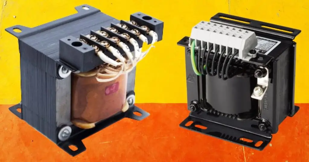
Explanation of Single-Phase Transformers A single-phase transformer is an electrical device designed to transfer electrical energy between two or more circuits through electromagnetic induction. Operating on the principle of Faraday’s Law of Induction, it primarily functions to either step up or step down voltage levels, facilitating efficient power distribution and utilization. These transformers are integral to electrical systems, ensuring that electrical energy is delivered safely and effectively to various loads.
Working of Single-Phase Transformers

Overview
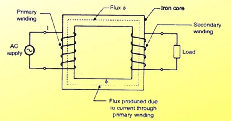
A single-phase transformer is an electrical device that transfers electrical energy between two or more circuits through electromagnetic induction. It is composed of several key components that work together to convert voltage levels and ensure efficient power distribution. These components include flux (ɸ), primary winding, iron core, secondary winding, AC supply, and load.
Components and Their Functions
AC Supply
The AC supply is the input power source that provides alternating current to the transformer. It connects to the primary winding and initiates the process of electromagnetic induction.
Primary Winding
The primary winding consists of coils of wire wound around the iron core. When an AC voltage is applied to this winding, it generates an alternating magnetic flux (ɸ).
Iron Core
The iron core is a crucial component that provides a low reluctance path for the magnetic flux. It is typically made of laminated iron to minimize eddy current losses and enhance the efficiency of magnetic flux transfer between the primary and secondary windings.
Flux (ɸ)
The alternating current flowing through the primary winding generates an alternating magnetic flux (ɸ) in the iron core. This flux is the medium through which energy is transferred from the primary to the secondary winding.
Secondary Winding
The secondary winding is another set of coils wound around the same iron core. The alternating magnetic flux (ɸ) induces an electromotive force (EMF) in the secondary winding, which can be used to supply power to a load.
Load
The load is the device or component that receives electrical power from the transformer. It is connected to the secondary winding and can range from household appliances to industrial machines.
Process of Energy Transfer
Flux Generation
When the AC supply energizes the primary winding, it produces an alternating current that flows through the coils. This current generates an alternating magnetic flux (ɸ) within the iron core.
Magnetic Flux Transfer
The alternating magnetic flux (ɸ) travels through the iron core, linking the primary and secondary windings. The iron core’s material ensures that the flux is efficiently transferred with minimal losses.
Induction in Secondary Winding
As the alternating magnetic flux (ɸ) passes through the secondary winding, it induces an alternating electromotive force (EMF) in the coils according to Faraday’s Law of Electromagnetic Induction. The magnitude of this induced EMF is proportional to the number of turns in the secondary winding and the rate of change of the magnetic flux.
Power Delivery to Load
The induced EMF in the secondary winding creates an alternating current that flows to the connected load. The voltage level of this current can be adjusted by changing the ratio of turns between the primary and secondary windings, allowing for voltage step-up or step-down as needed.
Applications and Uses
Residential Applications In residential settings, single-phase transformers are used to step down the high voltage from power lines to a safer, usable voltage for homes. They are essential for powering household appliances, lighting, and heating systems.
Commercial Applications Commercial buildings use single-phase transformers to supply power to office equipment, lighting, HVAC systems, and other essential services. These transformers ensure that electrical loads receive consistent and reliable power.
Industrial Applications In industrial settings, single-phase transformers are utilized in machinery, control systems, and other equipment requiring specific voltage levels. They are critical in processes such as welding, electroplating, and operating motors.
You may love to read our amazing post on : Three-Phase Transformers- Top 4 The Most Powerful Connection Types
The 5 Most Powerful Connection Tips
Tip #1 – Proper Grounding Techniques
Importance of Grounding
Safety and Performance Grounding a single-phase transformer is critical for both safety and performance. Proper grounding ensures that in the event of a fault, such as a short circuit, the electrical current will have a safe path to the ground, reducing the risk of electric shock, fire, and damage to equipment. Grounding also stabilizes voltage levels, improving the overall performance and reliability of the electrical system. By maintaining a consistent reference point, grounding helps to protect sensitive equipment from voltage fluctuations and transient surges.
Step-by-Step Grounding Process
Step 1: Select the Grounding Electrode Choose an appropriate grounding electrode, such as a grounding rod, plate, or a metallic water pipe, as per local electrical codes. The electrode must be made of conductive material like copper or galvanized steel.
Step 2: Prepare the Grounding Electrode If using a grounding rod, drive it into the ground to a depth specified by local codes, typically at least 8 feet. Ensure the rod is fully embedded to make effective contact with the earth.
Step 3: Connect the Grounding Conductor Use a grounding conductor, usually a copper wire, to connect the transformer’s grounding terminal to the grounding electrode. The conductor must be sized appropriately based on the transformer’s specifications and local electrical codes.
Step 4: Secure Connections Ensure all connections are tight and secure. Use appropriate connectors or clamps to attach the grounding conductor to the grounding electrode and the transformer’s grounding terminal. The connections should be free of corrosion and provide a solid, low-resistance path to ground.
Step 5: Inspect and Test After completing the grounding installation, inspect all components to ensure they comply with safety standards and local codes. Perform a ground resistance test to verify that the grounding system is effective. The resistance should typically be less than 5 ohms.
Common Grounding Mistakes to Avoid
Improper Electrode Installation Failing to drive the grounding rod to the required depth can result in poor grounding. Always ensure the rod is fully embedded and makes good contact with the earth.
Undersized Grounding Conductor Using a grounding conductor that is too small can lead to overheating and ineffective grounding. Always use a conductor sized according to the transformer’s specifications and local codes.
Loose Connections Loose or corroded connections can increase resistance and reduce the effectiveness of the grounding system. Regularly inspect and maintain all connections to ensure they remain secure and free of corrosion.
Incorrect Grounding Points Connecting the grounding conductor to inappropriate points, such as gas pipes or isolated metal objects, can compromise safety. Always connect to approved grounding electrodes.
Tip #2 – Correctly Matching Impedance
Understanding Impedance Matching
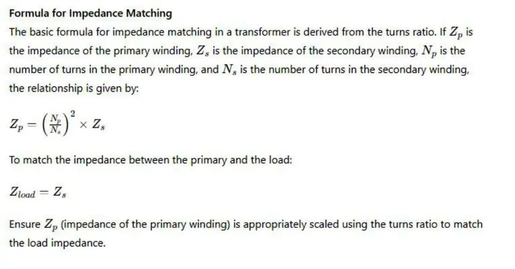
Basic Principles of Impedance Impedance is the measure of opposition that a circuit presents to the flow of alternating current (AC) and is composed of resistance (R), inductance (L), and capacitance (C). In transformer operation, impedance matching refers to ensuring that the impedance of the transformer matches the impedance of the load it supplies. This is crucial for optimizing power transfer and minimizing reflections that can cause inefficiencies and potential damage to the system.
Role in Transformer Operation When the impedance of the transformer and load are correctly matched, the maximum amount of power is transferred from the transformer to the load. Mismatched impedance can lead to power losses, overheating, and reduced performance, impacting the overall efficiency of the electrical system.
How to Measure and Match Impedance
Tools and Techniques for Measuring Impedance To accurately measure impedance, you can use tools such as an LCR meter (measures inductance, capacitance, and resistance) or an impedance analyzer. These instruments provide precise readings of the transformer and load impedance, helping you to identify any discrepancies.
Step-by-Step Process for Measuring Impedance
- Prepare the Equipment: Ensure the transformer and load are disconnected from the power source.
- Connect the LCR Meter: Attach the leads of the LCR meter to the primary winding of the transformer.
- Record the Measurement: Take note of the impedance value displayed on the meter.
- Repeat for Secondary Winding: Perform the same steps for the secondary winding if needed.
Guidelines for Ensuring Impedance Matching
- Identify Transformer Impedance: Determine the impedance of both the primary and secondary windings.
- Determine Load Impedance: Measure or calculate the impedance of the connected load.
- Use Matching Techniques: If there is a significant mismatch, use impedance matching techniques such as adding matching transformers, adjusting tap settings, or using impedance matching networks.

Impact on Efficiency and Performance
Effects of Proper Impedance Matching When impedance is correctly matched, the transformer operates at its highest efficiency, ensuring that the maximum amount of power is delivered to the load with minimal losses. This reduces the risk of overheating, extends the lifespan of the transformer, and ensures stable and reliable performance.
Consequences of Impedance Mismatch An impedance mismatch can cause several issues:
- Power Losses: Unmatched impedance can lead to significant power losses due to reflections and inefficiencies.
- Overheating: Excessive power dissipation can cause the transformer to overheat, potentially damaging internal components.
- Reduced Performance: The overall performance of the electrical system may be compromised, leading to unstable voltage and current levels.
Tip #3 – Ensuring Proper Cooling and Ventilation
Importance of Cooling in Transformers
How Overheating Affects Transformer Lifespan and Performance Overheating is one of the primary factors that can reduce the lifespan and performance of a transformer. Excessive heat accelerates the aging of insulation materials, leading to insulation breakdown and reduced dielectric strength. This can cause electrical failures, short circuits, and ultimately transformer failure. Overheating also increases the resistance in the windings, which can decrease efficiency and increase energy losses. In severe cases, it can cause physical damage to the transformer’s internal components, leading to costly repairs or replacements. Therefore, maintaining proper cooling and ventilation is essential to ensure the longevity and optimal performance of transformers.
Cooling Methods
Natural Cooling Methods Air Natural (AN) Cooling relies on natural air circulation to dissipate heat. The transformer is typically designed with radiators or fins to increase the surface area for heat dissipation. The pros include simple design, low maintenance, and cost-effectiveness. However, it has limited cooling capacity and may not be sufficient for high-load applications.
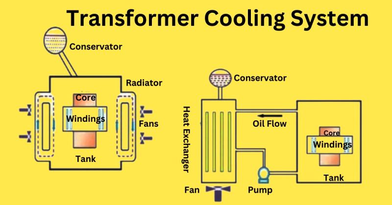
Oil Natural Air Natural (ONAN) Cooling uses oil as a coolant, which circulates naturally within the transformer. The heat generated by the windings is transferred to the oil, which then dissipates heat to the surrounding air through radiators. The pros are better cooling efficiency than air natural and suitability for medium-load applications. The cons include requiring regular oil maintenance and potential environmental concerns.
Forced Cooling Methods Air Forced (AF) Cooling uses fans to increase the airflow over the transformer’s surface, enhancing the cooling effect. The pros are improved cooling efficiency and the ability to handle higher loads. The cons are higher energy consumption and additional maintenance for fans.
Oil Forced Air Forced (OFAF) Cooling combines oil circulation with forced air cooling. Pumps are used to circulate the oil, and fans blow air over the radiators. The pros are high cooling efficiency and suitability for heavy-load applications. The cons are more complexity and expense, and higher maintenance requirements.
Pros and Cons of Each Method Natural Cooling is simple and low-cost but limited in cooling capacity. Forced Cooling offers higher efficiency and capacity but is more complex and expensive to maintain.
Transfer Cooling System Components

Core The core is the central part of the transformer, where the magnetic flux is generated. It must be kept cool to prevent overheating, which can degrade its magnetic properties.
Windings The windings are coils of conductive material (typically copper or aluminum) that generate heat when current flows through them. Efficient cooling is required to maintain their conductivity and prevent insulation breakdown.
Tank The tank encloses the transformer and is filled with insulating oil that helps to cool the core and windings. The tank must be designed to dissipate heat effectively.
Oil Flow Oil circulates within the transformer to absorb heat from the core and windings. This oil must be kept clean and at the correct level to ensure effective cooling.
Pump In forced oil cooling systems, a pump is used to circulate the oil more effectively, enhancing the cooling process.
Conservator The conservator is an expansion tank that accommodates the expansion and contraction of the insulating oil due to temperature changes. It helps maintain proper oil levels and pressure.
Heat Exchanger The heat exchanger transfers heat from the transformer oil to the surrounding air or water, facilitating cooling. It is often used in conjunction with forced cooling systems.
Fan Fans are used to increase air circulation over the transformer’s radiators or heat exchangers, enhancing the cooling effect.
Radiator Radiators are external components that provide a large surface area for the oil to dissipate heat into the surrounding air. They are critical for effective natural or forced air cooling.
Installation Best Practices
Guidelines for Installing Transformers to Ensure Adequate Ventilation Location: Install transformers in well-ventilated areas to ensure proper airflow. Avoid enclosed or confined spaces that can restrict ventilation.
Clearance: Maintain sufficient clearance around the transformer to allow for free airflow. Follow manufacturer recommendations for minimum clearance distances.
Orientation: Position the transformer so that cooling fins or radiators are oriented to maximize natural airflow or the effectiveness of forced air systems.
Ambient Temperature: Consider the ambient temperature of the installation site. Higher ambient temperatures may require enhanced cooling methods.
Obstructions: Ensure that there are no obstructions blocking the airflow to and from the transformer.
Tip #4 – Using the Right Connection Configuration
Overview of Connection Configurations
Explanation of Different Connection Configurations
| Configuration | Description | Applications |
|---|---|---|
| Delta (Δ) | Transformer windings are connected in a triangular loop, with each winding connected end-to-end, forming a closed circuit. | Industrial applications due to its ability to handle high power and provide stable three-phase voltage. |
| Wye (Y) | One end of each winding is connected to a common neutral point, while the other ends are connected to the power lines. | Residential and commercial applications because it provides a neutral wire for grounding and allows for both three-phase and single-phase power distribution. |
Choosing the Right Configuration for Your Needs
| Criteria | Delta Configuration | Wye Configuration |
|---|---|---|
| Voltage Requirements | Suitable for higher line voltages. | Preferred for systems needing a neutral point for grounding and lower line-to-neutral voltages. |
| Load Type | Ideal for balanced, three-phase loads (industrial settings). | Better for systems with mixed three-phase and single-phase loads (commercial buildings). |
| Current Capacity | Can handle higher currents (heavy-duty industrial applications). | Suitable for lighter loads and applications requiring both three-phase and single-phase power. |
| Safety and Grounding | Typically more complex for grounding. | Provides a neutral point for easier grounding, enhancing safety (residential and commercial applications). |
Step-by-Step Connection Process
| Connection Configuration | Steps |
|---|---|
| Delta Configuration | 1. Identify the Windings: Label each end of the transformer windings (A, B, C). 2. Connect the Windings: Connect the end of winding A to the start of winding B, the end of winding B to the start of winding C, and the end of winding C to the start of winding A, forming a triangular loop. 3. Connect the Load: Attach the load connections to the points where the windings join. |
| Wye Configuration | 1. Identify the Windings: Label each end of the transformer windings (A, B, C). 2. Create a Neutral Point: Connect one end of each winding to form a common neutral point (N). 3. Connect the Power Lines: Attach the other ends of the windings (A, B, C) to the respective power lines. 4. Connect the Load: Connect the load to the power lines and the neutral point if required. |
Troubleshooting Connection Issues
| Problem | Description | Solution |
|---|---|---|
| Unbalanced Loads | Can cause voltage fluctuations and overheating. | Ensure that the loads are evenly distributed across all phases. Consider using a Wye configuration with a neutral point to better manage single-phase loads. |
| Incorrect Connections | Can lead to short circuits and transformer damage. | Double-check all connections against the wiring diagrams before energizing the transformer. Use a multimeter to verify continuity and correct wiring. |
| Overheating | May occur if the transformer is overloaded or if there is poor ventilation. | Ensure that the transformer is operating within its rated capacity and that cooling systems are functioning properly. If necessary, upgrade to a transformer with a higher capacity. |
| Humming or Vibrations | Can indicate loose connections or magnetic imbalances. | Inspect all connections for tightness and ensure that the transformer is securely mounted. Check for any signs of mechanical damage. |
Tip #5 – Regular Testing and Maintenance
Importance of Regular Testing
| Importance of Regular Testing |
|---|
| Regular testing is essential for maintaining the health and safety of single-phase transformers. It helps in early detection of potential issues, ensuring that minor problems do not escalate into major failures. Regular testing also ensures compliance with safety standards and enhances the overall reliability and efficiency of the transformer. By performing routine tests, you can extend the lifespan of the transformer, reduce downtime, and minimize the risk of costly repairs or replacements. |
Types of Tests
| Type of Test | Description |
|---|---|
| Insulation Resistance Test | Measures the resistance of the insulation material to ensure it is intact and effective. High insulation resistance indicates good condition, while low resistance may indicate deterioration or damage. |
| Turns Ratio Test | Verifies the correct turns ratio between the primary and secondary windings, ensuring the transformer operates at the correct voltage levels. Deviations in the turns ratio can indicate winding damage or manufacturing defects. |
| Power Factor Testing | Assesses the transformer’s dielectric losses to evaluate the condition of the insulation system. High power factor readings can indicate insulation deterioration. |
| Oil Analysis | For oil-cooled transformers, analyzing the insulating oil can reveal the presence of contaminants and assess the oil’s dielectric strength. Regular oil analysis helps in detecting issues like moisture content, acidity, and dissolved gases. |
| Visual Inspection | Involves a thorough examination of the transformer’s external and internal components for signs of wear, corrosion, or damage. Regular visual inspections can help identify issues that are not detected by electrical tests. |
Maintenance Schedule
| Maintenance Task | Frequency |
|---|---|
| Visual Inspection | Monthly |
| Insulation Resistance Test | Annually |
| Turns Ratio Test | Annually |
| Power Factor Testing | Annually |
| Oil Analysis | Semi-Annually (for oil-cooled transformers) |
| Thermal Imaging | Annually |
| Load Testing | Annually |
| Cleaning and Tightening Connections | Annually |
Documentation and Record-Keeping
| Best Practices for Documentation and Record-Keeping |
|---|
| Maintaining accurate and detailed records of all tests and maintenance activities is crucial for effective transformer management. Documenting the results of each test, including date, time, and the technician’s observations, helps in tracking the transformer’s condition over time. Use a standardized format for recording data to ensure consistency and ease of analysis. Keep records of any repairs or replacements carried out, along with the details of the components used. Regularly review and update maintenance logs to ensure that all necessary tests and maintenance tasks are performed on schedule. Proper documentation also aids in regulatory compliance and can provide valuable insights during audits or inspections. |
FAQ on “Single-Phase Transformers”
Q: What is the primary function of a single-phase transformer?
A: It converts voltage levels in electrical circuits.
Q: Why is grounding important for single-phase transformers?
A: It ensures safety by preventing shocks and damage.
Q: How can impedance matching improve transformer performance?
A: It maximizes power transfer and minimizes losses.
Q: What are the common cooling methods for single-phase transformers?
A: Methods include natural air, ONAN, and forced air.
Conclusion
Regular testing and maintenance are crucial for the health and safety of single-phase transformers. By understanding and implementing proper grounding techniques, matching impedance correctly, ensuring adequate cooling, choosing the right connection configuration, and adhering to a rigorous testing and maintenance schedule, you can significantly enhance the efficiency, reliability, and longevity of your transformers. Consistent care and proactive measures not only prevent costly breakdowns and repairs but also ensure stable and uninterrupted power supply for various applications. Stay vigilant, keep detailed records, and follow best practices to maintain your transformers in peak condition.
