Starting Air System Mechanism
The starting air system in marine diesel engines is a critical mechanism that uses compressed air to initiate engine rotation. This system ensures the engine can start efficiently and reliably, even under heavy-duty conditions. Comprising essential components like air distributors, starting valves, and receivers, the starting air system manages the precise timing and flow of air to the engine cylinders.
Its role in engine operation cannot be overstated, as a malfunction in the starting air system could lead to engine failure or delays in critical operations. In this guide, we will explore how the system functions, focusing on the mechanism behind distributor direction changes and fuel cam reversal. These aspects are vital for efficient engine operation, especially during reversing or emergency maneuvers. By understanding these systems, you can ensure better maintenance, safety, and performance of marine diesel engines, making this an essential read for marine engineers in 2024.
Starting Air Mechanism Components

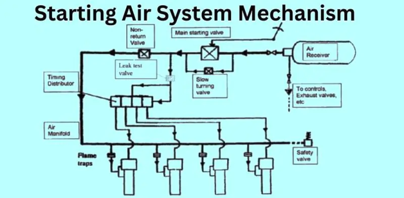
The starting air system in marine diesel engines is made up of several essential components that work together to initiate engine rotation by delivering compressed air. Below is a detailed description of each component and its function in the starting air mechanism.
Air Receiver
The air receiver is a pressurized storage tank that holds the compressed air necessary for starting the engine. It ensures that there is always a sufficient amount of air available to quickly and efficiently initiate engine rotation.
Main Starting Valve
The main starting valve regulates the release of compressed air from the air receiver into the engine’s cylinders. When the starting process is initiated, this valve opens, allowing air to flow through the system and into the engine to begin rotation.
Non-Return Valve
The non-return valve ensures that the compressed air flows in only one direction, preventing backflow into the air receiver or other parts of the system. This is vital for protecting the system from reverse pressure, which could cause damage or failure.
Air to Controls Exhaust Valves
Compressed air is directed to the exhaust valves during the starting process to control their opening and closing. Proper operation of the exhaust valves is essential to ensure efficient air distribution and engine rotation during startup.
Slow Turning Valve
The slow turning valve allows for the controlled, gradual rotation of the engine at low speeds during the starting process. This prevents hydraulic lock, reduces wear on engine components, and ensures that the engine can be gradually brought up to operating speed.
Leak Test Valve
The leak test valve is used to test for air leaks in the starting system before starting the engine. By ensuring the system is airtight, it helps prevent any failure during the actual startup process, guaranteeing the engine will receive the necessary pressure to start.
Timing Distributor
The timing distributor controls the precise timing and sequence of air delivery to each engine cylinder. It ensures that compressed air is supplied in the correct order, enabling smooth and efficient engine startup.
Air Manifolds
Air manifolds distribute compressed air from the air receiver to various parts of the starting system. They are essential for directing air to the appropriate locations, such as the exhaust valves, timing distributor, and cylinders.
Flame Traps
Flame traps are safety devices installed to prevent the risk of fire or explosion during the starting process. They stop flames from traveling back through the air intake and protect the starting air system from potential hazards.
Safety Valve
The safety valve is a critical protective feature that releases excess pressure if the air pressure within the system exceeds a safe limit. This prevents over-pressurization, which could damage system components or cause dangerous conditions.
Working Principle of the Starting Air System
The starting air system in marine diesel engines follows a precise process to deliver compressed air to the engine cylinders, initiating rotation. Here’s a detailed step-by-step explanation of how it works.
Compressed Air Supply
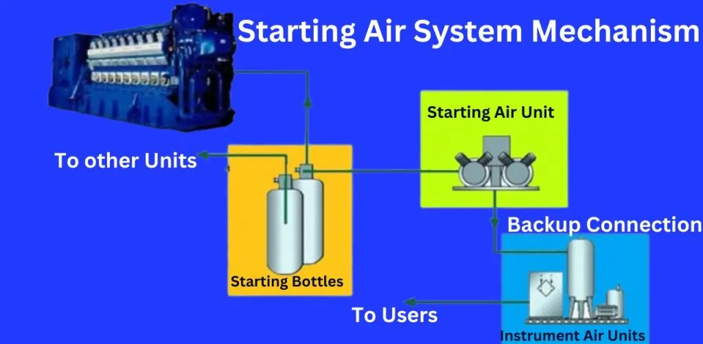
Compressed air is stored in starting air receivers and released when the engine starting process is triggered. This high-pressure air is essential for driving the pistons and creating initial engine movement.
Air Delivery to Cylinders
The starting air valves regulate the flow of compressed air into each cylinder. These valves open in coordination with the engine’s timing, allowing the air to enter at the exact moment to push the piston downward, setting the engine rotation in motion.
Role of the Air Distributor
The air distributor plays a critical role in controlling the sequence and timing of air delivery to each cylinder. It ensures the compressed air reaches the cylinders in the correct order, enabling smooth and continuous rotation during the startup process.
Continued Rotation
As the engine begins to rotate, the distributor maintains the flow of air to the cylinders, keeping the rotation steady until the engine reaches the speed necessary for combustion to take over. The distributor’s precise timing is crucial for avoiding misfires and ensuring a successful engine start.
How the Distributor Changes Direction
The air distributor plays a pivotal role in controlling the flow of compressed air to the cylinders during the engine start. Its precise operation is critical to ensure that air is delivered in the correct sequence for engine rotation, whether in the forward or reverse direction.
Role of the Air Distributor in Controlling Air to the Cylinders
The air distributor ensures that the compressed air reaches the engine cylinders in a timed sequence, pushing the pistons to create the necessary rotation. It coordinates with the camshaft to control the exact moment the air is delivered, ensuring efficient engine start-up.
Mechanism of Direction Change During Engine Start
The air distributor is designed to adjust depending on the direction in which the engine needs to rotate. During startup, the control valves inside the distributor change positions to modify the airflow. These valves shift based on whether the engine is required to rotate clockwise or counterclockwise, ensuring smooth engine operation in both directions.
Control Valves for Clockwise and Counterclockwise Rotation
For clockwise rotation, the distributor directs the air to the appropriate cylinders in a specific order. When the engine needs to rotate counterclockwise, the control valves adjust to reverse the airflow sequence. This flexibility is essential for changing the direction of the engine when needed, such as during maneuvering operations on a ship.
Interaction Between the Camshaft and the Air Distributor
The camshaft works closely with the air distributor during direction reversal. When the engine’s direction is switched, the camshaft’s timing shifts, signaling the distributor to modify the airflow. This synchronized interaction ensures that the distributor delivers air to the correct cylinders for either forward or reverse rotation, preventing misfires and ensuring smooth transitions.
This mechanism of directional control allows the air distributor to effectively manage the engine’s starting process, whether in normal operation or when reversing.
Mechanism for Reversing the Fuel Cam
The fuel cam mechanism is crucial for controlling the timing and amount of fuel injected into the engine’s cylinders. When the engine direction changes, the fuel cam must adjust accordingly to ensure proper fuel injection for efficient engine operation.
Explanation of the Fuel Cam Mechanism
The fuel cam regulates fuel injection by controlling the timing and duration of fuel delivery into the cylinders. It works in conjunction with the camshaft, which pushes the cam followers to open and close the fuel injectors at precisely the right moments, ensuring that the engine operates smoothly.
How the Reversing Mechanism Works
When the engine direction needs to change, the reversing mechanism shifts the position of the fuel cam. This is typically achieved through a mechanical linkage or hydraulic system that moves the camshaft and fuel cam into a new position. This shift allows the engine to maintain proper fuel injection timing for both forward and reverse rotations.
Role of the Camshaft and Cam Followers in Reversing
The camshaft plays a central role in reversing the fuel cam. As the engine direction changes, the camshaft adjusts its rotation, and the cam followers adapt their motion to the new timing pattern. The cam followers ensure that the fuel injectors open at the correct time, maintaining the necessary fuel flow for the new direction.
Impact on Fuel Injection Timing and Distribution
When the fuel cam is reversed, it alters the timing and distribution of fuel injection. In reverse rotation, the fuel must be injected earlier or later, depending on the engine’s operational needs. This adjustment ensures efficient combustion and smooth engine performance, preventing any misfires or fuel supply issues during directional changes.
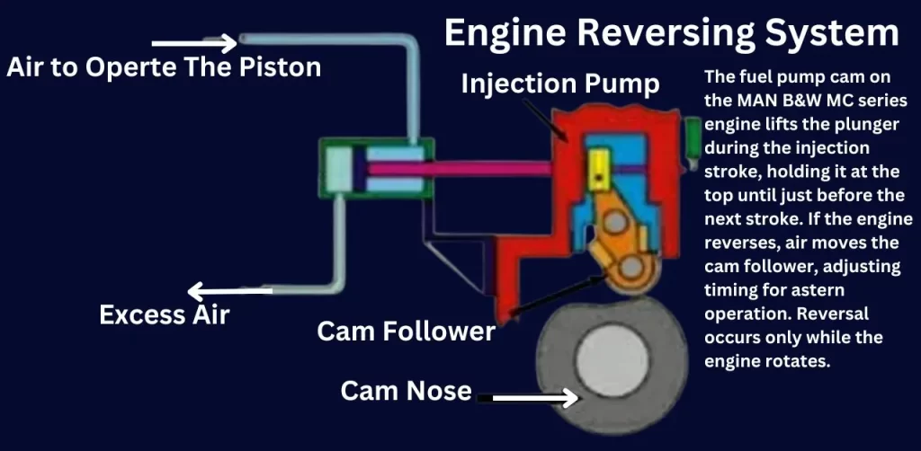
Fuel Pump Cam Mechanism on the MAN B&W MC Series Engine

The fuel pump cam on the MAN B&W MC series engine is designed to lift the fuel pump plunger during the injection stroke. The plunger is held at the top of its stroke while the cam follower remains on the cam’s peak. Just before the next delivery stroke, the follower returns to the base circle, allowing the fuel pump plunger to descend on the suction stroke.
Cam Follower and Injection Timing
At the start of the injection process, the cam follower moves up the slope of the cam as the camshaft rotates in an anticlockwise direction. If the engine reverses at this point, air enters the pneumatic cylinder, pushing the piston to the right. This action moves the cam follower to a position corresponding to the correct fuel pump timing for running astern.
Reversal Process and Engine Rotation
The reversal of the cam follower only occurs while the engine is rotating. If the engine stops after running ahead and is then restarted to run astern, the fuel pump followers will automatically move across as the engine rotates. This happens before fuel is admitted by venting the fuel pump puncture valves.
Micro Switch and Safety Measures
A micro switch on the left-hand side (LHS) detects whether the follower has successfully moved across. If not, an indicator light in the control room alerts the operator. Despite this, the engine will still start, even if the follower fails to move, possibly due to corrosion in the servo cylinder. In such cases, a high exhaust temperature deviation alarm will activate shortly after. Allowing the engine to start under these circumstances can be useful during confined water maneuvering.
Starting Air System Safety Measures
Safety is paramount in the operation of the starting air system in marine diesel engines. Proper safeguards are in place to ensure the system operates efficiently while minimizing risks. Here’s an overview of the key safety components and their roles.
Overview of Safety Valves
Safety valves are critical components in the starting air system, designed to release excess air pressure to prevent over-pressurization. When the air pressure exceeds a predetermined limit, the safety valve opens to discharge the extra air, ensuring the system remains within safe operating conditions. This prevents any damage to the components and avoids potential hazards like burst pipes or system failure.
Non-Return Valves in the Starting Air System
Non-return valves are essential for preventing backflow of air into the system. These valves ensure that air flows in only one direction, preventing any reversed flow that could disrupt the engine starting process or damage the air receivers. By securing one-way air movement, non-return valves protect both the engine and the starting air system from potential malfunction.
Prevention of Backflow and Air Pressure Regulation
Both safety and non-return valves work together to regulate air pressure and prevent backflow, which could otherwise cause severe system failures. By releasing excess pressure and stopping reverse air flow, these valves help maintain the stability of the system, ensuring smooth and safe engine start-up operations.
Troubleshooting Common Issues
Below is a table highlighting common problems encountered in the starting air system, along with solutions and preventive maintenance tips to ensure smooth operation.
| Issue | Description | Solution | Preventive Maintenance Tips |
|---|---|---|---|
| Improper Air Distribution | Air not reaching all cylinders, leading to uneven engine rotation. | Check the air distributor for clogs or misalignment; clean or replace parts. | Regularly inspect and clean the air distributor to prevent blockages. |
| Failure to Start | Engine fails to rotate despite compressed air supply. | Inspect starting air valves for malfunction or leakage; repair or replace. | Perform periodic valve checks for wear, and replace faulty components immediately. |
| Backflow in Air System | Air flowing backward into the starting air receiver or system lines. | Check non-return valves for damage; replace if necessary. | Regularly test non-return valves to ensure proper functioning. |
| Excessive Air Pressure | Over-pressurization causing potential damage to system components. | Ensure safety valves are operational; adjust or replace as needed. | Calibrate safety valves regularly to maintain proper pressure limits. |
| Air Leakages | Compressed air escaping from the system, reducing efficiency. | Inspect for leaks in piping, joints, and valves; seal or replace parts. | Conduct frequent pressure tests to detect leaks early. |
| Slow Engine Crank | Engine cranks slower than usual, indicating low air pressure. | Check air receiver pressure; refill if necessary, and inspect for leaks. | Monitor receiver pressure regularly and ensure there is adequate air supply. |
| Valve Timing Issues | Valves not opening or closing at the correct time, causing starting delays. | Adjust the timing of the starting air distributor. | Periodically synchronize and adjust valve timing for accurate operation. |
FAQ on “Starting Air System”
Q: How does a starting air system work?
A: It delivers compressed air to rotate the engine cylinders for starting.
Q: What is the starting air timing?
A: It’s the precise moment when compressed air enters the cylinders to start rotation.
Q: What is the starting air pressure?
A: Typical starting air pressure ranges from 20 to 30 bar.
Q: What is PSI?
A: PSI stands for pounds per square inch, a pressure measurement unit.
Conclusion
Understanding the starting air system mechanism is crucial for the reliable and efficient operation of marine diesel engines. This system plays a vital role in initiating engine rotation by delivering compressed air at the right time and sequence. Key components such as the air distributor, starting air valves, and safety features ensure smooth engine starts and safe operation.
To maintain optimal performance and safety, regular inspections, timely maintenance, and proper adjustments of the system’s components are essential. By adhering to safety measures, preventing common issues, and ensuring that the system is functioning efficiently, marine engineers can prevent costly breakdowns and maintain the longevity of the engine. Keeping the starting air system in top condition is a key factor in achieving consistent and trouble-free engine operations.
