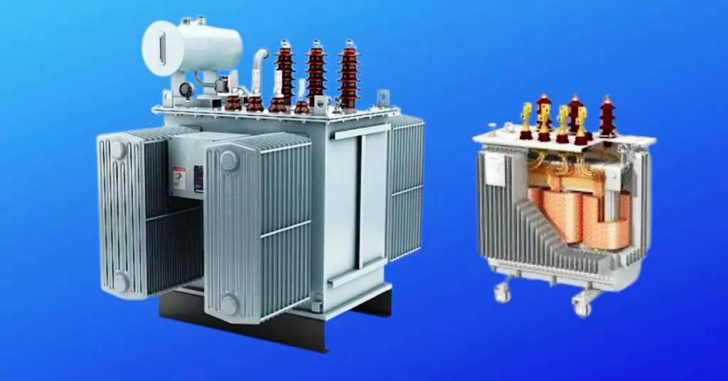
Three-Phase Transformers
Three-phase transformers are vital components in modern electrical systems, providing efficient Electrical power distribution across various applications. These transformers convert voltages in a three-phase electrical system, which is more efficient and reliable than single-phase systems, especially for industrial and commercial use. The connection configurations of three-phase transformers—such as star-delta, delta-star, delta-delta, and star-star—play a crucial role in determining their performance and suitability for specific applications.
Each configuration offers unique advantages, from stepping up or down voltages to handling different load types and ensuring balanced power distribution despite unbalanced currents on the primary side. Selecting the appropriate connection type is essential for optimizing transformer efficiency, reliability, and overall system performance, making them indispensable in both utility companies and industrial applications. Understanding these configurations helps in designing robust electrical systems that meet the growing demands of today’s energy landscape.
Three-Phase Transformer Working Principle
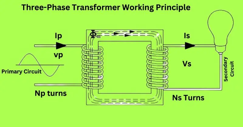
A three-phase transformer operates based on the principles of electromagnetic induction and is used to step up or step down voltages in a three-phase system. Here’s a breakdown of its working principle with the relevant components:
Primary Circuit
The primary circuit of a three-phase transformer is where the initial electrical energy is supplied. It consists of three primary windings connected either in star (Y) or delta (Δ) configuration.
- Primary Current (IpI_pIp): The current flowing through the primary windings.
- Primary Voltage (VpV_pVp): The voltage applied to the primary windings.
- Primary Windings (NpN_pNp turns): The number of turns in the primary winding which determines the transformer’s ability to step up or step down the voltage.
Secondary Circuit
The secondary circuit is where the transformed electrical energy is delivered. It also consists of three windings, configured similarly to the primary or differently depending on the desired transformation.
- Secondary Current (IsI_sIs): The current flowing through the secondary windings.
- Secondary Voltage (VsV_sVs): The voltage induced in the secondary windings.
- Secondary Windings (NsN_sNs turns): The number of turns in the secondary winding which determines the output voltage.
Working Principle
- Electromagnetic Induction: When an alternating current (IpI_pIp) flows through the primary winding, it creates a varying magnetic field in the transformer’s core.
- Magnetic Flux: This varying magnetic field induces a magnetic flux that links with the secondary winding.
- Induced EMF: According to Faraday’s Law of Electromagnetic Induction, this magnetic flux induces an electromotive force (EMF) in the secondary winding. The induced EMF is proportional to the rate of change of magnetic flux and the number of turns in the winding (NpN_pNp and NsN_sNs).
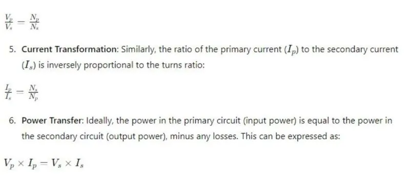
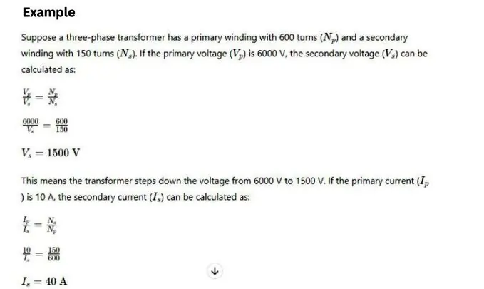
- Voltage Transformation: The ratio of the primary voltage (VpV_pVp) to the secondary voltage (VsV_sVs) is equal to the ratio of the number of turns in the primary winding (NpN_pNp) to the number of turns in the secondary winding (NsN_sNs). This can be expressed as:
Star-Delta (Y-Δ) Connection
Explanation and Diagram
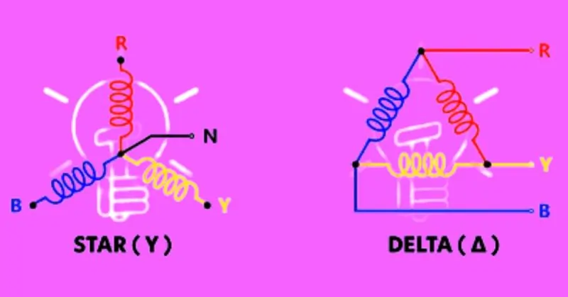
A Star-Delta (Y-Δ) connection involves connecting the primary winding of the transformer in a star (Y) configuration and the secondary winding in a delta (Δ) configuration. This setup is commonly used to step down high transmission voltages to lower distribution voltages.
How Star-Delta Connection Works
In a star-delta transformer, the primary winding is connected in a star configuration, which means one end of each winding is connected to a common neutral point, and the other ends are connected to the supply lines. The secondary winding is connected in a delta configuration, forming a closed loop. This configuration reduces the phase voltage on the primary side by a factor of 13\frac{1}{\sqrt{3}}31 (compared to the line voltage), which helps in reducing insulation requirements.
Visual Representation of the Configuration
Applications
- Common Use Cases: The star-delta connection is widely used in transmission and distribution systems to step down high voltages to a lower, more usable level for industrial and residential applications. It is also used in motor starting applications to reduce the starting current.
Advantages
- Stepping Down Voltages: This configuration is highly efficient for stepping down high transmission voltages to lower distribution voltages, making it ideal for power distribution networks.
- Grounding Benefits and Lightning Surge Protection: The star connection on the primary side allows the neutral point to be grounded, providing a path for fault currents and enhancing system stability. It also offers protection against lightning surges, which is crucial for maintaining system reliability.
Challenges
- Handling Unbalanced Loads: One of the main challenges with the star-delta configuration is managing unbalanced loads. Since the secondary side is delta-connected, any unbalance in the load can lead to circulating currents within the delta loop, potentially causing overheating and inefficiency. Careful load management and transformer sizing are essential to mitigate these issues.
Delta-Star (Δ-Y) Connection
Explanation and Diagram
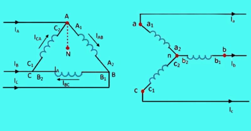
A Delta-Star (Δ-Y) connection involves connecting the primary winding of the transformer in a delta (Δ) configuration and the secondary winding in a star (Y) configuration. This setup is commonly used to step up voltages in high tension transmission systems.
How Delta-Star Connection Works
In a delta-star transformer, the primary winding is connected in a delta configuration, meaning each winding is connected end-to-end to form a closed loop. The secondary winding is connected in a star configuration, where one end of each winding is connected to a common neutral point, and the other ends are connected to the load.
Primary (Delta) Configuration:
- Terminals: A1,A2,B1,B2,C1,C2
- Currents:IAB,IBC,ICA
- Example: Current flows from A1 to A2 (through the load), B1 to B2, and C1 to C2 forming a closed loop.
Secondary (Star) Configuration:
- Terminals: a1,a2,b1,b2,c1,c2
- Neutral Point: N (formed by connecting one end of each winding together)
- Currents: Ia,Ib,Ic
Visual Representation of the Configuration
Applications
- Stepping Up Voltages in High Tension Transmission: The delta-star connection is widely used in power systems to step up the voltage from generation levels to higher transmission levels, facilitating efficient long-distance power transmission. It is also employed in creating a neutral point for grounding and enabling a three-phase four-wire system.
Advantages
- Dual Voltage Outputs: This configuration provides both line-to-neutral and line-to-line voltages, offering flexibility in supplying different voltage levels. The secondary side can provide a three-phase voltage with a neutral point, allowing for dual voltage outputs suitable for various load requirements.
- Flexibility in Load Handling: The delta-star connection allows for the accommodation of unbalanced loads better than some other configurations. The star-connected secondary provides a neutral point, which can be grounded to stabilize the system and manage unbalanced currents more effectively.
Challenges
- Insulation Requirements: The delta-star configuration requires careful attention to insulation, especially on the star side, where the phase voltage is √3 times the line voltage. This increases the stress on the insulation, necessitating higher insulation standards to prevent breakdowns.
- Phase Difference Issues: One challenge with the delta-star configuration is the inherent 30-degree phase shift between the primary and secondary windings. This phase difference can cause complications in systems where multiple transformers are used in parallel, requiring careful management to ensure proper synchronization and prevent circulating currents.
Delta-Delta (Δ-Δ) Connection
Explanation and Diagram
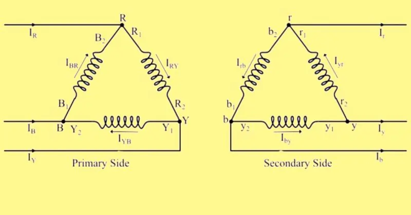
A Delta-Delta (Δ-Δ) connection involves connecting both the primary and secondary windings of a three-phase transformer in a delta configuration. This setup is particularly suitable for high-current, three-phase power loads and is often used in industrial applications where balanced load conditions are prevalent.
How Delta-Delta Connection Works
In a delta-delta transformer, the windings are connected in a closed loop or delta configuration. This means that the ends of each winding are connected to form a triangle, with each corner representing a phase. This configuration ensures that the line voltage is equal to the phase voltage and allows for high current flow through the windings.
The primary winding is connected in a delta configuration, and the corresponding secondary winding is also connected in a delta configuration. The secondary winding r1r2 corresponds to the primary winding R1R2, and the terminals R1 and r1 have the same polarity. Similarly, the polarity of terminal rrr connecting r1and b2 is the same as that of R connecting R1 and B2.
Visual Representation of the Configuration
Applications
- Suitable for High Current, Three-Phase Power Loads: The delta-delta connection is ideal for applications requiring high current and balanced three-phase power loads, such as industrial motors and heavy machinery. It is also commonly used in power distribution systems where large amounts of power need to be transferred efficiently.
Advantages
- No Phase Difference Between Primary and Secondary: One of the key benefits of the delta-delta connection is that there is no phase difference between the primary and secondary windings. This simplifies the design and operation of the system and reduces the risk of synchronization issues.
- Uninterrupted Power Supply Even if One Transformer Fails: Another significant advantage is that the delta-delta configuration can continue to supply power even if one transformer fails. This is known as the open-delta or V-connection, which allows the remaining two transformers to provide three-phase power at a reduced capacity.
Challenges
- High Current Flow Requires Close Placement to Source and Load: The high current flow through the delta-delta connection requires that the transformer be placed close to both the power source and the load. This minimizes the losses and ensures efficient operation. However, this requirement can limit the flexibility of the system and may necessitate additional infrastructure to support the placement of the transformers.
Star-Star (Y-Y) Connection
Explanation and Diagram
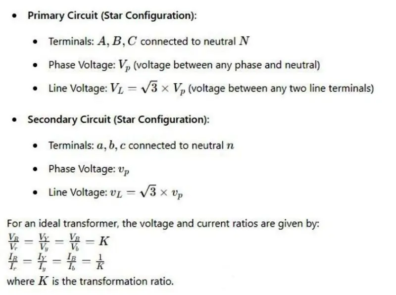
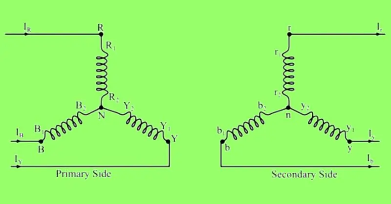
A Star-Star (Y-Y) connection involves connecting both the primary and secondary windings of a three-phase transformer in a star configuration. This setup is ideal for balanced load distribution and is commonly used in systems requiring a neutral point for grounding and three-phase four-wire systems.
How Star-Star Connection Works
In a star-star transformer, one terminal of each of the three windings on both the primary and secondary sides is connected to a common point known as the neutral point. The other ends of the windings are connected to the line terminals.
Visual Representation of the Configuration
Applications
- Ideal for Balanced Load Distribution: The star-star connection is well-suited for applications where balanced load distribution is critical, such as in large office buildings, commercial complexes, and industrial facilities.
Advantages
- Simplified Current Flow and Voltage Relationships: In the star-star configuration, the phase current is equal to the line current, simplifying the analysis and design of the system. The relationship between line and phase voltages ( VL = √3 x VP ) makes it easy to handle different voltage levels.
- Suitable for Three-Phase Four-Wire Systems: This configuration provides a neutral point, allowing for the creation of a three-phase four-wire system. This is beneficial for distributing both three-phase and single-phase loads and for grounding purposes.
Challenges
- Unbalanced Load Issues: One of the primary challenges with the star-star configuration is handling unbalanced loads. An unbalanced load can cause a shift in the neutral point, leading to unequal phase voltages and potential system instability.
- Harmonic Voltages: Without a neutral tie, large third harmonic voltages can appear in both primary and secondary windings. This can lead to insulation failures and interfere with communication lines, making it unsuitable for applications where telephone lines are run in parallel.
Powerful Connection Configurations
Importance of Choosing the Right Configuration
Selecting the appropriate transformer connection configuration is crucial for optimizing performance, efficiency, and reliability in power distribution systems. The choice depends on specific power needs, including voltage levels, current capacity, load types, and system requirements. Here are some critical configurations and their impacts:
- Star-Delta (Y-Δ) Connection:
- Applications: Stepping down high transmission voltages to lower distribution voltages.
- Advantages: Reduced insulation requirements, grounding benefits, and lightning surge protection.
- Challenges: Managing unbalanced loads and potential phase difference issues.
- Impact: This configuration is ideal for systems where stepping down voltage is essential, providing stable performance despite load imbalances.
- Delta-Star (Δ-Y) Connection:
- Applications: Stepping up voltages in high tension transmission.
- Advantages: Dual voltage outputs, flexibility in load handling.
- Challenges: Higher insulation requirements and phase difference complications.
- Impact: Suitable for high voltage transmission and versatile load management, essential for long-distance power distribution.
- Delta-Delta (Δ-Δ) Connection:
- Applications: High current, three-phase power loads.
- Advantages: No phase difference between primary and secondary, uninterrupted power supply even if one transformer fails.
- Challenges: Requires close placement to source and load due to high current flow.
- Impact: Reliable for industrial applications with high current demands, ensuring continuous operation.
- Star-Star (Y-Y) Connection:
- Applications: Balanced load distribution.
- Advantages: Simplified current flow and voltage relationships, suitable for three-phase four-wire systems.
- Challenges: Unbalanced load issues and harmonic voltages.
- Impact: Ideal for systems requiring neutral grounding, though it needs careful management of unbalanced loads to avoid performance issues.
Impact on Efficiency and Reliability
The efficiency and reliability of a power system heavily depend on the chosen transformer configuration. Each configuration has unique characteristics that influence transformer performance:
- Efficiency: Properly matched configurations minimize losses and maximize power transfer efficiency. For example, the star-delta configuration reduces insulation requirements, enhancing efficiency in stepping down voltages.
- Reliability: Configurations like delta-delta offer uninterrupted power supply capabilities, improving system reliability in critical applications. Star-star configurations provide neutral grounding, essential for safety and stability.
Future Trends
Innovations and emerging trends in transformer configurations aim to enhance performance, efficiency, and adaptability in modern power systems:
- Smart Transformers: Integration of digital monitoring and control technologies to optimize performance in real-time, adapt to load changes, and predict maintenance needs.
- Renewable Integration: Configurations designed to handle the variability and distributed nature of renewable energy sources like solar and wind, ensuring stable and efficient power conversion.
- Advanced Materials: Development of new materials for windings and cores to reduce losses, improve thermal performance, and increase overall efficiency.
- Modular Designs: Flexible, modular transformer designs that can be easily upgraded or reconfigured to meet changing power demands and system expansions.
FAQ on “Three-Phase Transformers”
Q: What is the primary function of a three-phase transformer?
A: It converts electrical energy between different voltage levels.
Q: What are the common connection types for three-phase transformers?
A: Star-Delta (Y-Δ), Delta-Star (Δ-Y), Delta-Delta (Δ-Δ), and Star-Star (Y-Y).
Q: Why is the Star-Delta (Y-Δ) connection used?
A: To step down high transmission voltages
Q: What are the challenges of using a Delta-Delta (Δ-Δ) connection?
A: Managing high current flow near the source and load.
Conclusion
Recap of the Top 4 Connection Types
We’ve explored four powerful transformer connection configurations:
- Star-Delta (Y-Δ): Ideal for stepping down high transmission voltages to lower distribution levels, providing benefits like reduced insulation requirements and lightning surge protection.
- Delta-Star (Δ-Y): Used for stepping up voltages in high tension transmission, offering dual voltage outputs and flexibility in load handling.
- Delta-Delta (Δ-Δ): Suitable for high current, three-phase power loads, ensuring no phase difference between primary and secondary and maintaining uninterrupted power supply even if one transformer fails.
- Star-Star (Y-Y): Perfect for balanced load distribution, simplifying current flow and voltage relationships, and supporting three-phase four-wire systems.
Final Thoughts on the Importance of Selecting the Right Transformer Configuration
Choosing the appropriate transformer configuration is critical to optimizing power system performance, efficiency, and reliability. Each configuration has distinct advantages and challenges, making it essential to match the transformer to specific power needs and system requirements. Proper selection ensures efficient voltage transformation, minimizes losses, and enhances overall system stability and resilience.
Encouragement for Further Reading and Exploration
The field of transformer technology is continually evolving, with innovations aimed at improving efficiency, integrating renewable energy sources, and enhancing real-time monitoring and control. For those interested in diving deeper, exploring advanced transformer technologies and their applications can provide valuable insights into the future of power systems.
Consider further reading on topics like smart transformers, renewable energy integration, advanced materials, and modular designs to stay updated on the latest trends and advancements in transformer technology. These developments will play a crucial role in shaping the future of energy distribution and management, making it an exciting area for ongoing study and exploration.
