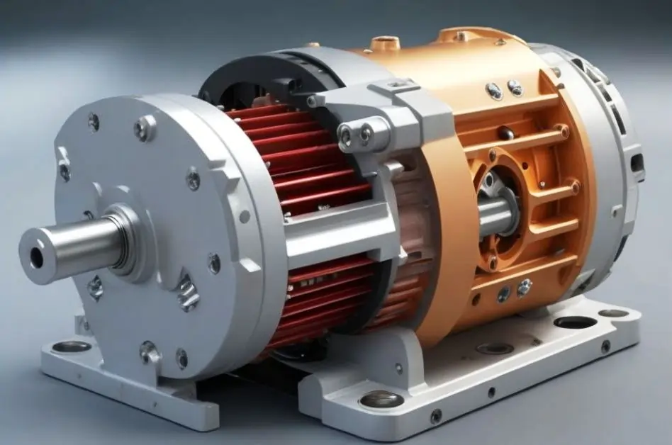
Types Of Electric Motor
Imagine a machine that can turn electricity into movement, almost like magic. That’s exactly what an electric motor does. By harnessing the power of magnets and wires, these motors create motion that can spin, rotate, or even push things in a straight line.
Electric motors are incredibly versatile, running on different types of electricity—from the batteries in your gadgets to the power from your wall outlet. They come in various shapes and sizes, finding their way into everything from industrial machinery and vehicles to the everyday appliances and tools you use at home.
Some motors are massive, driving the engines of ships or powering large-scale industrial equipment. Others are tiny, quietly working inside fans, power tools, and even watches. What’s even more fascinating is that electric motors can also reverse their magic, converting movement back into electricity, like when they help a car slow down and save energy.
In this blog post, we’ll explore the different types of electric motors and how they work. Whether you’re just curious or trying to choose the right motor for a specific job, we’ve got you covered. Get ready to dive into the world of these silent helpers that keep our machines running smoothly, no matter the size or application.
Types of Motors on Board Ships
Various types of electric motors are used onboard ships to power different equipment and systems. The most commonly used motors include:
1. Induction Motors (AC Motors)
- Single-phase induction motors: Typically used for smaller applications like pumps or fans where less power is required.
- Three-phase induction motors: Widely used for more demanding applications such as main propulsion systems, large pumps, compressors, and winches. These motors are known for their robustness and efficiency in marine environments.
2. Synchronous Motors
- Used for large, precise applications where speed needs to be synchronized with the power supply frequency. These motors are found in applications like power generation or large ship machinery where stable operation is required.
3. DC Motors
- Less common but still found on some vessels, especially for equipment requiring precise speed control, such as in hoists, cranes, and small auxiliary systems.
4. Brushless DC Motors
- Found in specific applications where compact size and high reliability are important, like navigation systems and automated control systems.
5. Hydraulic Motors
- While not purely electrical, hydraulic motors are driven by electrical pumps and used in winching systems and heavy lifting applications on board.
What is an Electric Motor?
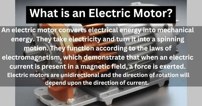
An electric motor converts electrical energy into mechanical energy. They take electricity and turn it into a spinning motion. They function according to the laws of electromagnetism, which demonstrate that a force is exerted when an electric current is in a magnetic field.
Electric motors are unidirectional, and the direction of rotation will depend upon the current direction.
How does an electric motor work?
An electric motor is a machine designed to convert electrical energy into mechanical movement, operating on principles that differ from those of a generator. The magic behind an electric motor lies in electromagnetism—the phenomenon where electricity flowing through a magnetic field creates a force that either pushes or pulls.
This force is what drives the internal components of the motor, causing them to spin and generate motion.
Key Components of an Electric Motor:
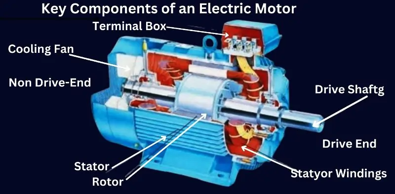
An electric motor is a complex machine composed of several key components that work together to convert electrical energy into mechanical movement. Understanding these components is essential to grasp how an electric motor functions effectively.
1. Terminal Box
The terminal box is the enclosure where electrical connections are made. It houses the terminals that connect the motor’s internal wiring to the external power supply. The terminal box ensures safe and organized connections, making it easier to manage the motor’s power input.
2. Cooling Fan
The cooling fan is a critical component that prevents the motor from overheating. It is typically mounted on the rotor or shaft and operates by drawing air across the motor’s surface. This airflow dissipates heat generated during operation, ensuring the motor runs efficiently and prolonging its lifespan.
3. Driving Shaft
The driving shaft is the component that transmits mechanical power from the motor to the connected machinery or load. As the rotor spins, the driving shaft rotates, delivering the torque necessary to drive various applications, from industrial machines to household appliances.
4. Stator Winding
The stator winding consists of coils of wire wound around the stator’s core. When electricity passes through these windings, it generates a magnetic field that interacts with the rotor. The strength and configuration of the stator winding determine the motor’s performance, including its speed and torque.
5. Rotor
The rotor is the rotating part of the motor that is set in motion by the magnetic field generated by the stator. It is connected to the driving shaft and is responsible for converting electrical energy into mechanical movement. The rotor can be of different types, such as squirrel-cage or wound, depending on the motor design.
6. Stator
The stator is the stationary part of the motor that surrounds the rotor. It contains the stator winding and provides the magnetic field needed to drive the rotor. The stator’s design and construction are crucial for the motor’s efficiency and performance.
7. Drive End
The drive end of the motor refers to the side where the driving shaft extends out to connect with the load or machinery. This end is typically equipped with bearings that support the shaft and reduce friction, allowing smooth and efficient transmission of power.
8. Non Drive-End
The non-drive end is the opposite side of the motor from the drive end. While it does not connect to the load, it often houses components such as the cooling fan and additional bearings that support the rotor and maintain balance within the motor during operation.
Motor Specifications: A Detailed Overview
Motor specifications provide critical information about the motor’s performance, capabilities, and compatibility with specific applications. Understanding these specifications is essential for selecting the right motor for your needs. Below are the key motor specifications to consider:
- Power Rating (kW or HP): This indicates the motor’s power output, typically measured in kilowatts (kW) or horsepower (HP). It defines the amount of work the motor can perform.
- Voltage Rating: Specifies the operating voltage required by the motor, such as 230V, 400V, or 690V. Ensuring the correct voltage rating is crucial for optimal motor performance.
- Current Rating (Amps): The current rating defines how much current the motor draws during operation. It helps in selecting appropriate protection devices like circuit breakers.
- Speed (RPM): Measured in revolutions per minute (RPM), this defines how fast the motor’s shaft rotates. Different applications may require motors with different speed ratings.
- Frequency (Hz): Indicates the motor’s operating frequency, typically 50Hz or 60Hz, depending on the region or application. Matching the frequency to the power supply is essential for smooth operation.
- Efficiency (%): The efficiency rating of a motor shows how effectively it converts electrical power into mechanical energy. Higher efficiency motors are more energy-saving and cost-effective.
- Torque (Nm): Torque is the rotational force the motor generates, measured in Newton-meters (Nm). It is crucial for applications that require high starting or continuous load handling.
- Enclosure Type: Defines the motor’s protection level against environmental factors like dust, moisture, or heat. Common enclosure types include TEFC (Totally Enclosed Fan Cooled) and IP (Ingress Protection) rated motors.
- Duty Cycle: Describes how long the motor can run under specified conditions. It’s expressed as continuous, intermittent, or periodic duty, which helps in choosing motors for varying operational needs.
- Insulation Class: This indicates the thermal durability of the motor’s insulation material. Classes such as Class B, F, or H show the maximum temperatures the insulation can withstand without damage.
- Mounting Type: The way the motor is installed, such as foot-mounted, flange-mounted, or shaft-mounted. Choosing the correct mounting type ensures proper alignment and installation.
- Starting Method: Some motors specify starting methods like direct-on-line (DOL), star-delta, or soft starters, which influence how the motor starts under load and the initial surge current.
Types of Electric Motor
AC Motor
AC Motor Components
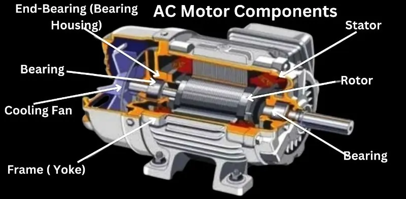
An AC motor is a versatile and reliable machine widely used in various industrial and household applications. Understanding its key components helps in appreciating how it efficiently converts electrical energy into mechanical motion. Here’s a detailed look at the essential components of an AC motor:
1. End-Bearing (Bearing Housing)
The end-bearing, housed within the bearing housing, is crucial for supporting the motor’s rotating components. It ensures smooth rotation of the rotor by reducing friction and wear. The bearing housing securely holds the bearings in place, protecting them from contaminants and ensuring the motor operates with minimal noise and vibration.
2. Housing
The housing is the outer shell that encloses and protects the internal components of the motor. It acts as a protective barrier against external elements like dust, moisture, and physical damage. The housing also aids in heat dissipation, helping to maintain the motor’s operational temperature within safe limits.
3. Bearing
Bearings are mechanical components that support the rotor and allow it to rotate with minimal friction. They play a critical role in ensuring the longevity and efficiency of the motor by minimizing wear and tear on the rotating parts. High-quality bearings contribute to the motor’s smooth and quiet operation.
4. Cooling Fan
The cooling fan is an essential part of the AC motor that helps regulate its temperature. Mounted on the rotor or within the housing, the fan circulates air over the motor’s components, dissipating heat generated during operation. This cooling process is vital for preventing overheating and ensuring the motor operates efficiently and reliably over time.
5. Frame (Yoke)
The frame, also known as the yoke, provides structural support to the motor. It holds the stator in place and forms the main body of the motor. The frame is typically made of durable materials like cast iron or aluminum, designed to withstand the mechanical stresses and environmental conditions the motor may encounter during operation.
6. Stator
The stator is the stationary part of the motor that generates the magnetic field required for the motor’s operation. It consists of windings or coils arranged around the inner surface of the housing. When an AC current passes through these windings, it creates a rotating magnetic field that induces movement in the rotor, driving the motor’s operation.
7. Rotor
The rotor is the rotating part of the AC motor that is driven by the magnetic field produced by the stator. It is connected to the output shaft, which transmits the motor’s mechanical power to the load. The rotor’s design, which may be of the squirrel-cage or wound type, is critical in determining the motor’s efficiency, speed, and torque.
Advantages of AC Motor
AC motors offer several advantages that make them popular in various applications:
- Efficiency: AC motors are highly efficient, converting approximately 85% of incoming power into mechanical output. They don’t suffer from overheating, braking, or rapid wear and tear.
- Longevity: These motors have a long lifespan, typically requiring only bearing replacements during their entire working life. Bearing replacement is cost-effective and straightforward, and AC motor bearings need periodic lubrication. Their durability makes them suitable for demanding conditions.
- Low Noise: AC motors operate quietly, making them ideal for settings where noise reduction is important, such as in the hospitality industry (restaurants, hotels, etc.).
- Adaptability: AC motors are versatile and flexible. They can operate with a simple on/off switch and offer reversible operation. This adaptability is valuable for applications requiring variable speed and power output, serving multiple users.
- Variety: AC motors come in various shapes and sizes, catering to specific industrial needs and accommodating multiple power sources.
- Simplicity: These motors have a straightforward design with only one moving part. The stator design is similar for synchronous and asynchronous AC motors, keeping production costs low and ensuring longevity.
- Cool Operation: AC motors do not have brushes and commutators, which can generate heat due to friction. This absence of friction components leads to cooler operation and improved efficiency.
- Ease of Starting: AC motors have a simple starting mechanism, requiring minimal additional components. Excitation is typically the only requirement to operate an AC machine.
- Speed Control: Changing the frequency of AC power can easily adjust the speed of the motor, providing convenient speed control.
- Single-Phase Operation: AC motors can be operated using single-phase input for three-phase machines, eliminating the need for three-phase power sources.
Types of AC Motors Explained:
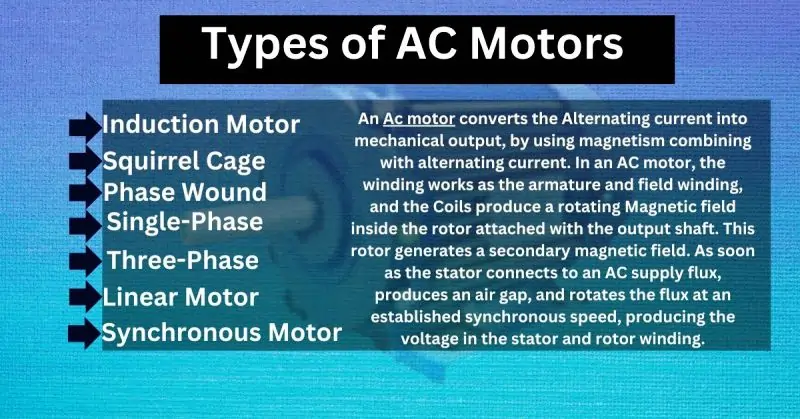
- Induction Motor:
- Induction motors use electricity to create rotating motion.
- They are used in lights, fans, motors, and generators.
- Ideal for high-torque and high-speed applications.
- It is efficient and requires minimal maintenance.
- Used in home appliances and easy to operate.
- Squirrel Cage Induction Motor:
- Part of the induction motor family.
- Known for reducing abnormal noise.
- Phase Wound Induction Motor:
- Another type of induction motor uses slip rings.
- Offers specific motor characteristics.
- Single-Phase Induction Motor:
- Converts single-phase AC power into mechanical power.
- Common in household appliances.
- Three-Phase Induction Motor:
- Converts 3-phase AC power into mechanical power.
- Widely used in industrial applications.
- Linear Motor:
- Generates linear force instead of rotational force.
- Used in sliding doors and actuators.
- Synchronous Motor:
- Converts AC into mechanical energy at a chosen frequency.
- Maintains synchronization of speed and supply current frequency.
- Includes Reluctance and Hysteresis motors.
DC Motor
In a Direct current motor, DC power gets converted into Mechanical Power. DC motor works on the principle that when a conductor carrying current is placed in the magnetic field, an exertion of force develops the torque.
Types of DC Motors
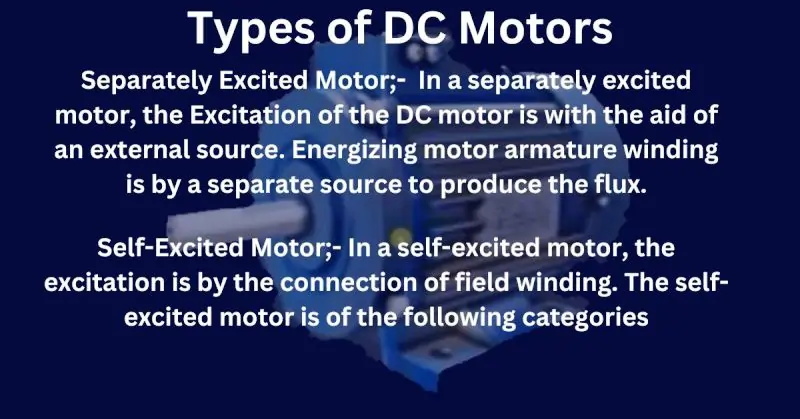
Separately Excited Motor;- In a separately excited motor, the Excitation of the DC motor is with the aid of an external source. Energizing motor armature winding is by a separate source to produce the flux.
Self-Excited Motor;- In a self-excited motor, the excitation is by the connection of field winding. The self-excited motor is of the following categories.
Shunt Motor
Shunt motors are a type of direct current (DC) motor. Shunt motors have a winding in their field with many twists, making a strong magnetic field.
The armature winding, on the other hand, can handle higher electric current. Why? Because the power (or torque) these motors produce depends on the armature’s electric current and the magnetic field’s strength.
A cool thing about shunt motors is that they’re “self-excited.” That means they don’t need an outside source to energize their field and armature windings.
In simple terms, shunt motors are built to handle a lot of current and use it to generate powerful motion.
Type of Shunt Motor
Series Motor
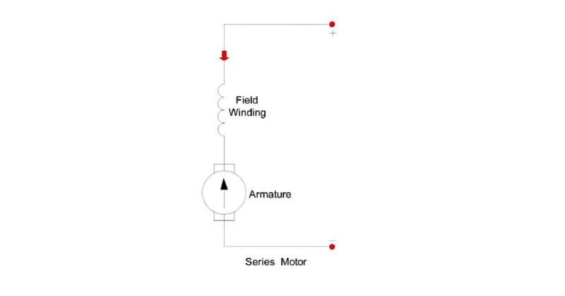
A series motor is a type of direct current (DC) motor. What’s special about it is that it has two windings connected in a series, and they both carry the same electric current.
Now, where do we find these series motors in action? They’re not everywhere because they’re best suited for situations where you need much power to start a machine. Think about elevators and hoists that need a big push to start moving. That’s where you often find series motors doing their job.
In simple terms, series motors are like the heavy lifters of the motor world. They’re the muscle when you need to move something hefty, but you don’t see them in everyday gadgets because they’re built for heavy-duty tasks.
Compound wound motor
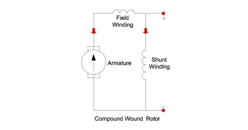
Compound wound DC motors are like the best of both worlds in the motor realm. They mix two other motor types: series wound and shunt wound.
Let’s break it down:
Series Wound Motors: These motors are all about powering up quickly. They give a big push to get things moving but may need to improve at maintaining a steady speed once they’re running.
Shunt Wound Motors: Conversely, these motors are like the marathon runners. They can keep a steady pace once they start and are known for their efficient speed regulation.
Now, back to compound wound motors. They take the strong starting boost from series wound motors and pair it up with the speed control finesse of shunt wound motors. It’s like having a motor that’s great at sprinting and excellent at keeping a consistent speed in a marathon.
These motors are handy when you need a powerful kickstart and the ability to keep things running smoothly. So, when you see compound wound DC motors, know they’re the best of both worlds, offering the advantages of high starting torque and efficient speed regulation.
Steps to Improve Power Factor in Motors
If you’re dealing with poor power factor in your motors, don’t worry; there are simple steps to fix it:
- Reduce Motor Idling: Motors often run when they’re not doing any real work, and this idling operation can lower the power factor. So, if a motor doesn’t need running, turn it off. It’s like switching off a light when you leave the room to save energy.
- Maintain Voltage and Balance: Motors work best when they get the right amount of electricity at the right balance. If the voltage is too high or too low or the phases aren’t balanced, it can mess up the power factor. Regular checks and adjustments can keep things in line.
- Install Capacitors: One of the most effective ways to fix power factor issues is by using capacitors. These handy devices help balance the electrical load, making motors run more efficiently. It’s like adding weights to a seesaw to keep it level.
By following these steps, you can ensure your motors work efficiently and use electricity wisely. It’s not just good for your motors but also for your energy bills and the environment. So, remember to reduce idling, maintain voltage and balance, and use capacitors when needed to keep your motors in top shape.
Motors Being Washed with Seawater
Seawater washing of motors is not a standard practice because seawater can cause significant damage to electrical equipment due to its high salt content and conductivity. However, motors on board are often exposed to humid, salty air and may accidentally come in contact with seawater. Here’s how seawater can affect motors and the precautions taken:
Effects of Seawater on Motors:
- Corrosion: The salt in seawater can lead to corrosion of the motor’s metal components, especially the windings, bearings, and casing. This degrades the motor’s mechanical integrity and reduces its lifespan.
- Electrical Short Circuits: Seawater is highly conductive, so exposure can cause short circuits within the motor, damaging the windings and other electrical parts.
- Insulation Breakdown: The moisture and salts can penetrate the motor’s insulation, leading to insulation failure and increasing the risk of electrical faults.
Preventive Measures:
- Enclosure Protection (IP Rating): Most motors used on ships have high Ingress Protection (IP) ratings, such as IP55 or IP66, to prevent water and salt ingress. These enclosures ensure the motor’s internal components remain dry even if exposed to seawater.
- Regular Maintenance: Motors exposed to a marine environment require frequent cleaning and maintenance. If a motor is accidentally washed with seawater or exposed to a marine atmosphere:
- Freshwater Cleaning: The first step is to flush the motor with fresh water to remove salt deposits. This helps prevent corrosion and electrical shorts.
- Drying: After cleaning, the motor should be thoroughly dried using heated air or in a drying oven to remove any moisture that could degrade the insulation.
- Insulation Testing: Post-washing, an insulation resistance test using a Megger should be conducted to ensure the insulation has not been compromised.
- Anti-corrosion Coatings: Some shipboard motors are coated with anti-corrosion paints or varnishes to protect against the harsh marine environment. This coating prevents direct exposure of metal parts to salty air or water.
- Space Heaters: Many marine motors are fitted with space heaters to prevent condensation buildup when the motors are idle, reducing the risk of moisture damage.
How to Increase Insulation Without Dismantling the Motor
Improving the insulation of a motor without dismantling it can be achieved through several practical methods that enhance the insulation’s resistance and longevity. These steps are commonly used in preventive maintenance to ensure the motor operates efficiently without needing a complete teardown.
1. Cleaning the Motor
Dirt, dust, and moisture can reduce the effectiveness of motor insulation. Regularly cleaning the motor’s exterior and cooling vents helps prevent contaminants from affecting insulation. Using dry compressed air or vacuuming the motor can remove dirt buildup, improving its performance.
2. Applying Insulation Varnish
One of the most effective ways to boost insulation without dismantling the motor is by applying a high-quality insulation varnish. This varnish can be sprayed or brushed onto accessible parts of the motor’s windings. It helps seal cracks and enhances the dielectric strength of the insulation, preventing breakdowns caused by moisture and contaminants.
3. Baking the Motor
If moisture has penetrated the insulation, baking the motor in a controlled oven can remove the moisture without dismantling the motor. This process, done at a low temperature, helps restore the insulation’s integrity and prevents future failures due to dampness.
4. Using Space Heaters
For motors exposed to high humidity, installing space heaters near the motor can prevent moisture buildup, maintaining insulation strength. These heaters are placed externally and do not require motor dismantling, but they keep the motor dry during shutdowns or idle periods.
5. Performing Regular Insulation Resistance Testing
Regularly testing the motor’s insulation using an insulation resistance tester (Megger) can help identify any deterioration in the insulation before it becomes a problem. If low resistance is detected, targeted steps like applying insulation varnish or drying techniques can be used to restore insulation levels without disassembly.
Induction Motor Principle
An induction motor is an asynchronous AC motor, meaning that it operates at a speed less than the synchronous speed. In this motor, the supply is provided to the stator, and the rotor receives an induced electromotive force (EMF) through electromagnetic induction.
Principle of Operation:
When a multi-phase AC supply is applied to the stator windings, it creates a rotating magnetic field. This rotating field moves at synchronous speed and cuts through the rotor, inducing an EMF in the rotor windings due to Faraday’s law of electromagnetic induction.
If the rotor circuit is closed (for example, in a squirrel-cage rotor), the induced EMF causes a current to flow through the rotor windings. This rotor current produces its own magnetic field. According to Lenz’s Law, the rotor’s magnetic field acts in opposition to the stator’s magnetic field, trying to align with or “catch up” to the rotating magnetic field of the stator.
However, the rotor never reaches synchronous speed because, at that point, no relative motion between the rotor and stator fields would exist, and no EMF would be induced in the rotor. Instead, the rotor settles at a speed slightly less than the synchronous speed, achieving a constant speed based on the load. This constant speed is key to the operation of induction motors in various industrial and commercial applications.
How to Test Insulation Resistance for an Induction Motor
Testing the insulation resistance of an induction motor is essential for assessing the health of the motor’s windings and ensuring that the insulation is intact. This helps to prevent potential failures due to insulation breakdown. The most common method for testing insulation is using a megohmmeter (also known as a megger). Below are the steps and guidelines for conducting this test:
Step 1: Safety Precautions
- Turn Off Power: Ensure that the induction motor is completely de-energized and isolated from the power source.
- Discharge Capacitors: If the motor has capacitors, discharge them to prevent any residual charge.
- Check for Dangerous Voltages: Verify that there is no live voltage in the motor windings using a multimeter.
- Use Personal Protective Equipment (PPE): Wear appropriate PPE, such as insulated gloves and safety glasses.
Step 2: Prepare the Megohmmeter
- Set up the megohmmeter as per the manufacturer’s instructions. Typically, the testing voltage ranges from 500V to 1000V DC, depending on the motor’s voltage rating.
- Make sure the test leads are in good condition and securely connected to the megger.
Step 3: Connect the Megohmmeter
- Connect the Test Leads:
- Connect one lead to the stator winding or the motor terminal.
- Connect the other lead to the motor frame or ground (earthing point).
Step 4: Perform the Insulation Test
- Initiate the Test: Press the test button on the megohmmeter to apply the test voltage.
- Observe the Reading: The megger will display a resistance value in megohms (MΩ). Hold the test for 60 seconds to get a stable reading.
Step 5: Analyze the Results
- Insulation Resistance Values:
- For new or recently rewound motors, the insulation resistance should generally be above 100 MΩ.
- For older motors, a reading above 1 MΩ is typically considered acceptable, though the value should be higher for better safety.
- Compare the Reading with the motor manufacturer’s recommended minimum insulation resistance value, which is often 1 MΩ per kV of motor voltage rating plus an additional safety factor.
Step 6: Repeat the Test for All Windings
- Conduct the insulation test for each winding phase-to-ground:
- Phase U to Ground
- Phase V to Ground
- Phase W to Ground
- Record the readings for each phase to identify any variations that could indicate potential insulation issues.
Step 7: Discharge the Motor Windings
- After testing, discharge any residual charge from the motor windings by connecting a grounding wire to the terminals. This ensures safety before reconnecting the motor to the power supply.
Interpretation of Results
- High Insulation Resistance: Indicates that the winding insulation is in good condition.
- Low Insulation Resistance: Suggests possible damage, moisture ingress, or aging insulation. Further investigation or maintenance may be needed before the motor is put back into operation.
What is Mutual Induction?
Mutual induction is the phenomenon where a change in the current flowing through one coil induces a voltage in a nearby coil. This occurs because a changing current creates a varying magnetic field, which can pass through adjacent coils and induce an electromotive force (EMF) in them. Mutual induction is governed by Faraday’s Law of Electromagnetic Induction, which states that the induced EMF is proportional to the rate of change of magnetic flux.
How Does Mutual Induction Work?
- It involves two coils placed close to each other, called the primary and secondary coils.
- When an AC current flows through the primary coil, it generates a changing magnetic field.
- This changing magnetic field induces a voltage in the secondary coil, causing current to flow if a closed circuit is present.
Applications of Mutual Induction
Mutual induction is the principle behind transformers, wireless chargers, and inductive sensors, playing a crucial role in power transmission and various electronic devices.
What is Single Phasing?
Single phasing is a condition that occurs when one of the three phases in a three-phase power supply is lost or fails. This results in an unbalanced power supply to the connected three-phase equipment, such as motors, which can cause severe damage if not detected and corrected promptly.
Effects of Single Phasing on Three-Phase Motors
- Overheating: When single phasing occurs, the remaining phases must carry the extra load, leading to excessive heat generation in the motor, which can damage its components.
- Reduced Torque: The motor’s output torque decreases significantly, making it difficult for the motor to start or causing it to stall during operation.
- Increased Current Draw: The motor compensates by drawing more current through the remaining phases, which can lead to overheating of the windings and potential failure.
Causes of Single Phasing
Single phasing can result from several issues, including:
- A broken power line or conductor.
- Faulty contactors that fail to connect all three phases.
- A blown fuse in one of the phases.
How to Protect Against Single Phasing
To prevent equipment damage and ensure safe operation, protecting against single phasing is crucial. Devices like phase failure relays can detect phase loss and automatically shut down the equipment, safeguarding the motor and other connected devices from damage.
Where Are Synchronous Motors Used Onboard a Ship?
Synchronous motors play a significant role in marine applications, particularly in electric ship propulsion and podded propulsion systems. These motors have been used for ship propulsion since the inception of the idea due to their many advantages over other motor types.
Electric Ship Propulsion
Synchronous motors are widely utilized in electric ship propulsion because they offer several benefits compared to induction motors. These advantages include:
- Cost savings: Over the long term, synchronous motors can lead to cost savings due to their efficiency and operational durability.
- Mechanical design simplicity: Synchronous motors are often preferred due to their simpler mechanical design, which makes them more reliable in demanding marine environments.
- Easier repairs: Their design allows for easier maintenance and repair compared to induction motors, reducing downtime and service costs.
Podded Propulsion
Synchronous motors are also commonly used in podded propulsion systems, where their ability to produce high power output makes them ideal for large ships. These motors can generate up to 100 MW, which is necessary for driving large vessels efficiently. Podded propulsion systems, where the motor and propeller are integrated into a single unit outside the ship’s hull, rely heavily on synchronous motors due to their power and precision.
Disadvantages of Synchronous Motors Onboard
Despite their many advantages, synchronous motors have some disadvantages:
- Size and Weight: As the power output of a synchronous motor increases, its size and weight also grow, making them heavier and more complex compared to other motor types.
- Need for Starting Applications: Synchronous motors require a dedicated starting application because they cannot start by themselves. Frequency converters are often used to start the motor and provide precise speed control during operation.
- Higher Cost: While they offer better performance, synchronous motors are generally more expensive than induction motors that provide the same power output, making them a more costly option in initial installations.
FAQ on ” Types Of Electric Motor
Q: What are the main types of electric motors?
A: The main types are DC motors and AC motors.
Q: How do AC motors differ from DC motors?
A: AC motors use alternating current, while DC motors use direct current.
Q: Can you give examples of AC motor types?
A: Sure, some examples are induction motors and synchronous motors.
Q: What’s a common application of DC motors?
A: DC motors are commonly used in tools, appliances, and electric vehicles.
Blog Post Conclusion
Electric motors are secretly everywhere in our daily lives, doing important jobs like keeping us cool with fans and running big factory machines.
We discussed the numerous electric motor types created for certain tasks and power requirements.
There’s a motor for every purpose, from the reliable induction motor to the precise synchronous and versatile DC motor.
On the other hand, DC motors offer simplicity and come in different types to suit specific needs.
Knowing the right capacitor size and what causes motor losses is important to make electric motors work well.
Whether you’re picking an appliance for your home or a motor for your machines at work, the things we’ve learned can help you choose wisely.
