Engine over speed failure
Engine over speed failure is a phenomenon that can happen at any time. Sometimes it’s easy to miss the warning signs. Other times, it can be hard to catch the issue before it causes a severe problem. In both cases, it’s essential to take action.
Due to engine overspeeding, I have received major breakdown reports on Diesel generators and Main Diesel Engines. In most cases, I have found the breakdowns due to the malfunctioning speed device. Due to the over speed of engines, severe damage to the Engine and associated alternator have been observed. In most cases, the Over-speeding of the Engine was caused due to the malfunctioning of the engine governor and fuel injection pumps. In a few instances, Governor’s drive has been the cause of overspeeding.
An over the speed of the Engine will significantly damage the main components like the Crankshaft, Engine bed plate, cylinder liners, and complete power pack of the Engine, including the valve drive mechanism, Turbochargers, and Generator.
In this post, we will cover Engine over-speed failure and try to help the readers to understand Engine over-speed failure.
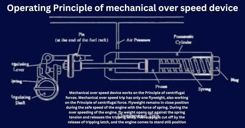
Operating Principle of mechanical over speed device

Engine overspeed occurs when an engine operates beyond its designed maximum RPM, which can lead to severe damage or failure. This situation is often managed by a governor system that regulates fuel supply to the engine. The system typically includes several key components:
- Regulating Lever: The regulating lever controls the fuel flow to the engine. It adjusts the position of the fuel rack based on the engine’s speed, thereby managing the engine’s RPM.
- Spring: A spring is connected to the regulating lever to maintain tension. This spring ensures that the regulating lever returns to its default position when the engine speed decreases, helping to prevent overspeed.
- Regulating Shaft: The regulating shaft connects the regulating lever to other components of the governor system. It translates the lever’s movement into rotational motion, which influences the fuel rack’s position.
- Pin (at the end of the fuel rack): The pin is located at the end of the fuel rack and interacts with the regulating shaft. Its position directly affects the amount of fuel delivered to the engine, thereby controlling the engine speed.
- Air Pressure: In some systems, air pressure is used to assist in controlling the fuel rack position. Increased air pressure can help to move the regulating lever or shaft, thereby adjusting the fuel supply to prevent overspeed.
- Pneumatic Cylinder: The pneumatic cylinder uses air pressure to move a piston. This movement can either increase or decrease fuel supply to the engine by interacting with the regulating shaft or fuel rack.
- Piston: The piston inside the pneumatic cylinder responds to changes in air pressure. Its movement controls the regulating shaft’s position, thereby adjusting the fuel rack to either accelerate or decelerate the engine.
- Spring: A second spring within the pneumatic cylinder ensures that the piston returns to its original position when air pressure is reduced. This action helps regulate the engine speed and prevent overspeed.
- Plug: The plug acts as a safety device within the governor system. In the event of excessive engine speed, the plug may engage to block fuel flow, thereby preventing further acceleration and potential overspeed.
Together, these components work in harmony to regulate the engine’s fuel supply, ensuring that it operates within safe RPM limits and preventing the potentially devastating effects of engine overspeed. Proper maintenance and regular checks of these components are crucial for ensuring reliable engine performance and avoiding costly overspeed failures.
Over speed, trip device stops the engine completely when the safe speed of the Engine exceeds.
Mechanical over speed device works on the Principle of centrifugal forces. Mechanical over speed trip has only one flyweight, also working on the Principle of centrifugal force. Flyweight remains in close position during the safe speed of the engine with the force of spring. During the over speeding of the engine, fly weight opens out against the spring tension and releases the tripping latch. Fuel supply is cut off by the release of tripping latch, and the engine comes to stand still position.
The flyweight is held to the drive shaft by a spring when the engine over speeds, the centrifugal force overcomes the resistance of the spring, and the flyweight moves away from the shaft.
During this position, the latch is tripped by the rotating flyweight, which releases the spring-loaded plunger. The plunger pushes against the fuel cutout lever, which moves the fuel pump control to the no injection position, and the engine stops.
Always put the latch in re-set position before re-starting the engine. The action is completed by the arm in re-set position with the help of re-set lever on the shaft. Make use of fuel cut out cam installed on the control shaft of the engine. During manually stopping operation of the engine, starting lever of the engine moves toward the stop position. Cam turns off the fuel cut off lever and shuts the fuel supply off.
Electronic over speed trip

The Magnetic Speed Pickup (MPU)

MPU is an instrument for detecting the speed of an Engine.
Magnetic speed pickup works on the principle of Faraday’s law.
The Engines flywheel is of magnetic material. Installing magnetic pickup is effortless without any additional attachment to a shaft. The following three factors affect the output voltage of magnetic pickup.
- Voltage increases when the speed of the controlled magnet increased.
- The increase in the air gap between the magnetic pickup and the gear tooth will decrease the voltage of the magnetic pickup.
- Voltage waveform will be determined by the size of the gear teeth relative to the size of the pole piece.
The gap between the end of the Magnetic Pickup and the gear teeth should be at-
0.25mm to 1.02 mm at the nearest point
Zero gaps between the MPU and flywheel teeth will damage the MPU. RMS value of an adequately installed MPU will be 50 Vac.
Magnetic Pickup Description

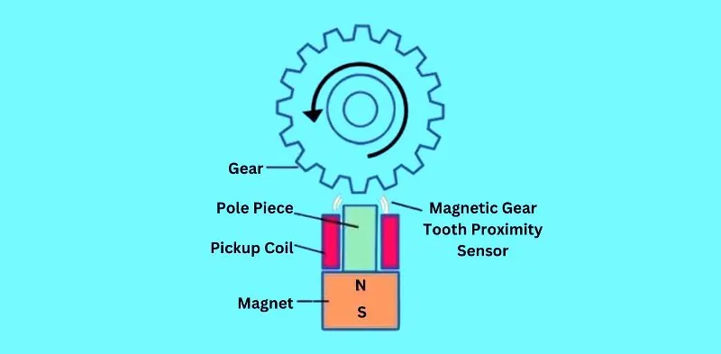
A Magnetic Pickup is a sensor designed to detect the speed and position of rotating components, such as gears, by responding to changes in magnetic flux. It plays a crucial role in various applications, including engine speed monitoring and position sensing. The key components of a magnetic pickup and their functions are as follows:
- Gear: The gear is the rotating component that the magnetic pickup monitors. As the gear rotates, its teeth pass by the sensor, causing variations in the magnetic field around the pickup.
- Pole Piece: The pole piece is the part of the magnetic pickup that focuses and directs the magnetic field. It helps to concentrate the magnetic flux generated by the magnet, ensuring that the pickup is sensitive to the proximity of the gear teeth.
- Pickup Coil: The pickup coil is a wound wire that generates an electrical signal in response to changes in the magnetic field. As the gear teeth pass by the sensor, the changing magnetic flux induces a voltage in the coil, which can be measured to determine the speed and position of the gear.
- Magnet: The magnet in the magnetic pickup generates a steady magnetic field. This field interacts with the gear teeth as they pass by, causing fluctuations in the magnetic flux. The magnet typically has a North (N) and South (S) pole, which creates the magnetic field necessary for the sensor’s operation.
- N and S (North and South Poles): The North and South poles of the magnet are critical for creating the magnetic field that the pickup coil responds to. As the gear teeth move through the magnetic field, they cause disturbances in the flux, which the pickup coil converts into an electrical signal.
- Magnetic Gear Tooth Proximity Sensor (Flux Change Indicating Gear Tooth Proximity): This sensor detects the proximity of the gear teeth based on changes in the magnetic flux. As each gear tooth approaches the pole piece, the magnetic flux increases, and as it moves away, the flux decreases. These changes are captured by the pickup coil, providing precise information about the gear’s speed and position.
In summary, the magnetic pickup functions by using a magnet and pole piece to create a magnetic field, which is altered by the passage of gear teeth. The pickup coil senses these changes in magnetic flux and generates an electrical signal corresponding to the gear’s rotation. This technology is widely used in various industrial and automotive applications to accurately monitor rotational speeds and positions.
What causes Engine over speed
In most cases, negligence in the maintenance of the over speed was the cause of failure.
The cause of Engine over speed failure is due to the malfunctioning of the Engine Governor and Fuel Injection pumps. Governor is installed on an engine to control the engine’s speed irrespective of load on the Engine. The governor controls Engine speed, with the control of fuel supply to the engine.
If the Governor cannot perform its function for some reason, then the Engine will over speed. Malfunctioning of the Governor is due to the failure of the Governor’s internal parts. Failure of the governor drive is the common reason for the over speeding of engine.
If the Governor loses control of the Engine and the Engine gets over speed, then, in that case, the over speed device must operate and stop the engine by cutting off the fuel supply to the Engine.
The Main causes of Engine over speed
- Faulty magnetic Pick up unit
- Sudden removal of load
- Increased throttle due to mechanical or electrical device
- Disturbed setting adjustments in governor
- Increased starting fuel limit
- Speed gain setting out of limit
- Faulty Injectors
- Disturbed setting in control panel
Over speed trip in Generator
Over speeding of a Generator is the most undesired situation in any Diesel Generator. If a Diesel generator continues to over speed, It will cause the most disastrous results. This situation will result from improper installation, commissioning of over-speed devices by unauthorized and unqualified technicians/Engineers.
Damages due to over speed of Engine
Over speed of an engine cause the major damage to the crankshaft, valve actuating mechanisms, valve, and valve seats, Camshaft, Turbocharger, Piston, Cylinder Liners and the Generator.
Consequent due to the over speed of engine could be very costly affair.
As per the recommendations of international standards, over speed device of any Diesel generator engine is supposed to operate at 115% of the Engine operating system. In the old design of engines, mechanical over speed device was in use. But in the latest design of the Engine, mechanical over speed device is obsolete. . Engine over speed control is through the electronic device,
If an over-speed device fails to control the speed and the Diesel generator continues to run above the permissible limit of speed, the over speeding of the diesel engine driving an electric generator could cause most Diesel generators to fly apart.
Testing procedure of over speed tripping device
Formula for Engine Overspeed Limit:

Where:
- Maximum Rated RPM is the maximum safe RPM as specified by the engine manufacturer.
- Overspeed Percentage is the percentage above the maximum rated RPM that is considered as the overspeed threshold (usually defined by engine manufacturers or industry standards).
Example Calculation:
If an engine has a maximum rated RPM of 2000 and the overspeed limit is set at 10%, the overspeed RPM limit would be calculated as:

Thus, the engine’s overspeed limit would be 2200 RPM.
This formula helps determine the RPM beyond which the engine should not be operated to avoid potential damage or failure.
There are different procedures for the other kind of over-speed devices on Diesel Generators. These devices are Electronic, mechanical, and a combination of both methods. Always conduct the tests on the offload condition of the diesel generator.
To test the electronic over speed device is to re-set the tripping set point to the lower limit for safety reasons. Start the engine and let the Engine operating conditions normalize. After the normalization of engine parameters, slowly increase the speed of the Engine. Observe the alarm and tripping RPM of the Engine. On completion of the test, re-set the tripping set back to the specified limit of over-speed.
For the Diesel generating sets with mechanical over speed, increase the engine’s speed and observe the speed at which the engine trips.
Carry out the re-setting operation on the device.
Engine over-speed warning
The Engine’s electronic device will give the engine’s warning signal over speed signal at 110% above the nominal speed. The warning signal is always set at 5 % less than the tripping speed of the Engine. Attend to the Engine over-speed warning signal without waiting for the Engine to trip.
Real-life incident
This incident occurred in a factory with SKL make Diesel generator. The engine was operating at full load. The engine started over speeding. Warning signals for the over speed was mal-functioning. Operate didn’t hear the abnormal sound from the engine soundproof control room. Engine speed increased slowly at 100 % load. The operator only came to know after the Engine was in a standing still position. The operator rushed to the engine room after the blackout. Operator observed the following significant damages to the engine and the alternator
- The crankcase door of the no8 unit was flown entirely apart.
- The connecting rod was protruding out of the crankcase.
- The piston got separated after getting damaged from the piston pin area.
- Alternator-damaged parts were flown out in various directions.
Engine repairs were done. All the damaged parts were replaced. The engine was made operational and re-commissioned.
I have attended the case of failure to carry out the Failure analysis. The customer had tried the Engine and loaded the Engine before I reached the site.
During the Engine at load, I observed the Engine and monitored all the parameters. After about 1 hour of engine operation, I heard the obnoxious sound from the Engine due to the engine over-speeding. I rushed for the emergency stop button and immediately stopped the Engine.
After cooling down the Engine, I started investigating the cause of the Engine over speeding. During the investigation, I got the Governor removed to send the Governor for the functional test to the workshop. Governor Sent the necessary tests to the workshop. No abnormality was detected in Governor.
During my further investigation, I have observed the splines of the governor drive shaft were worn entirely out except three splines slightly in good condition. The reason was the poor transmission of the drive to the Governor. The Governor’s drive shaft was not transmitting the proper drive, and the Governor was slowing down. The slowing down of Governor Speed, Governor, was increasing the fuel supply to maintain its speed.
Over speed, the device was not in contact with the crankshaft gear due to the missing device drive gear. This was the main cause of Engine over speed failure for this case.
On further investigation revealed that the operator removed the gear as the device was tripping the Engine frequently. The operator didn’t realize the maladjustment of the over-speed device.
Ignorance and poor operator knowledge have caused significant damage to the Engine and massive loss to the factory production due to Engine over speed failure.
I have observed that Engine over speed failure has taken place in many instances due to insufficient knowledge of the equipment. Factory operators don’t get proper attention for the engine operations. Factory owners are sometimes Pound Foolish pennywise. They purchase the costly Diesel generator but employ operators with poor operation and maintenance knowledge for the operation and upkeep and face Engine over speed failure.
FAQs on Engine Overspeed
Q- What is engine overspeed, and why is it dangerous?
A- Engine overspeed is when an engine exceeds its maximum RPM, risking severe damage or failure.
Q- What are the common causes of engine overspeed?
A- Malfunctioning governors, sudden load loss, and mechanical failures.
Q- How can engine overspeed be prevented?
A- Regular maintenance and reliable overspeed protection systems.
Q- What should be done if an engine overspeed event occurs?
A- Shut down the engine immediately and inspect for damage.
Blog Conclusion
Engine overspeed failure is a critical concern that can lead to catastrophic damage, costly repairs, and potential safety hazards. Understanding the causes, effects, and preventive measures is essential for maintaining engine longevity and operational efficiency. Regular maintenance, proper engine calibration, and the use of reliable overspeed protection systems are key strategies in mitigating the risks associated with engine overspeed. By staying vigilant and adhering to manufacturer guidelines, operators can ensure that engines perform optimally within safe operating limits, thereby safeguarding both the equipment and those who rely on its performance. Remember, preventing overspeed failure isn’t just about protecting machinery—it’s about ensuring safety and reliability in every application.
