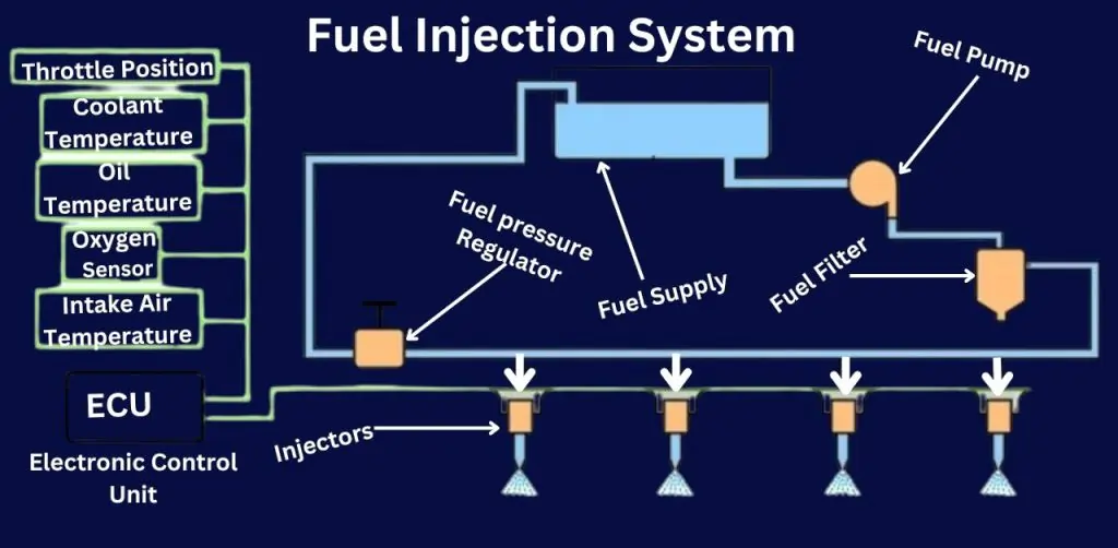
Fuel Injection System
A diesel engine’s fuel injection system is a crucial component. It delivers the right amount of fuel into the combustion chamber at the right time. fuel injection system should be well maintained and for that Engineers should have a thorough knowledge of it. Hence marine engineers should understand the system for the proper maintenance and trouble-free working of the system.
Fuel injection systems will be in the scope of this article. We will explain the different part, their function, and common problems. We’ll also talk about different types of fuel injection systems and their good and bad points. This blog post will provide important information to both marine engineers and Diesel power plant professionals.
Fuel Injection System Principles and Operation
The injection process in the combustion chamber takes place due to the high compression pressure produced by tightly fitted pistons in the cylinder liners. Fuel Injection Pump delivers the metered quantity of fuel for the proper air and fuel ratio. Fuel is delivered inside the cylinders at very high pressure and broken into a very fine spray with droplets of a few microns by Fuel Injectors. The fuel achieves this process at very high pressure forced through small orifices. In modern diesel engines trend is to raise the number of orifices making them smaller and achieving the pressure. In some of the Diesel Engines, the injection pressure is 375 bar.
Fundamentals of Fuel Injection Systems
The fundamental principle of the Fuel Injection system revolves around three essential elements:
Fuel: The process begins with Fuel Injection pumps supplying the required fuel for combustion at the correct pressure to the nozzles. These nozzles then break down the fuel into tiny droplets, creating a homogeneous mixture within the combustion chamber.
Heat: Adequate heat is generated to ignite the fuel within the combustion chamber during the compression stroke of the Engine’s operational cycles.
Air: Air is introduced during the suction stroke through natural aspiration or Turbocharger in turbocharged Engines. This ensures the complete combustion of the air-fuel mixture, optimizing the engine’s performance.
Type Of Fuel injection system of diesel engine
The fuel Oil system of Marine Diesel Engine is divided into the following two categories.
- Fuel Supply system
- Fuel Injection system
Fuel Supply system
The fuel supply system is designed to supply suitable fuel for the fuel injection system. The fuel system further consists of the listed systems
Piping system for bunkering purposes
Fuel storage system
Fuel transfer system
Fuel Treatment system
Piping system for bunkering purposes
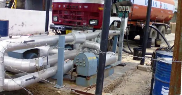
A pipeline is a network made up of pipes, fittings like valves and joints, pumps (or compressors for gas pipelines), and booster stations (which are intermediate pumping points along the pipeline). These booster stations house pumps or compressors. The pipeline also connects to storage facilities and has intake and outlet structures.
In simple terminology, the pipeline is the network of pipes working together. It includes pipes, valves, and joints to control the flow, pumps or compressors to move things through the pipes, and booster stations that help the process. The pipeline connects to storage places and has points where things can come in or go out. It’s a way to transport things from one place to another using a system of connected pipes and equipment.
Fuel storage system
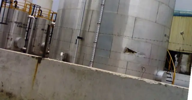
A fuel storage container is a small tank for keeping petrol or similar products, holding less than 230 liters. On the other hand, a fuel storage tank is a closed container for holding petroleum or similar products, with a capacity of more than 230 liters.
Bulk storage tanks are like big containers that can hold a lot of fuel. This is really useful because you won’t run out of fuel quickly. It helps work go smoothly because workers won’t have to leave the work area to get more fuel. They can stay focused on their tasks and not waste time refueling elsewhere.
Fuel Transfer system
In the fuel transfer system, fuel is received and stored in the storage tanks. Heaters are provided in the HFO storage tanks to maintain the correct pour point. From the storage tanks, the fuel continuously circulates. From the circulation system, fuel is transferred to fuel settling tanks through a controlled valve. This valve controls the supply of fuel to the settling tanks as per the requirement. In the settling tank, gross water and solids get settled down at the bottom.
From the settling tank, fuel is supplied to the fuel treatment units. Centrifuged oil is passed to the daily service tanks. From the daily service tank, fuel passes to the mixing unit through the three-way valve. Consumption of fuel is metered through a flow meter installed in the system. Fuel supply pumps supply the fuel to the engine-driven fuel pump. From the engine-driven pump, fuel is supplied to the fuel injection system through fuel filters. The viscosity meter installed in the system will control the fuel temperature to maintain the correct viscosity of the fuel for efficient combustion. A pressure-regulating valve installed in the system will regulate the fuel supply at constant pressure to the engine-driven pump.
The viscosity meter installed in the system will control the fuel temperature to maintain the correct viscosity of the fuel for efficient combustion. A pressure-regulating valve installed in the system will regulate the fuel supply at constant pressure to the engine-driven pump.
A diesel tank is incorporated into the system and is connected to the fuel supply system via a three-way cock. The purpose of the mixing tank is to collect the circulated fuel and supply the fuel in case the day tank is empty.
Various remote-operated safety devices are included in the system for the low-level alarms and remotely operated tank valves to close in the event of a fire.
Various remote-operated safety devices are included in the system for the low-level alarms and remotely operated tank valves to close in the event of a fire.
Fuel Treatment System: ==> Marine Centrifuge Separator Types: The best tutorial in 23-24
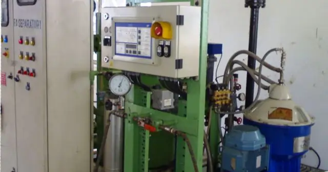
Fuel injection system
Fuel Injection Pump
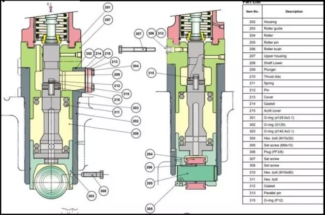
The FIP (fuel injection pump) performs the following functions.
- Supply and inject the metered fuel to cylinders as per the requirement of the load
- Supply the fuel at the correct time with respect to the firing order.
- Fuel Injection pump provides the fuel at pressure to injectors more than the injection pressure with a metered quantity.
Types of Fuel injection system
- Jerk type Pump
- The common rail injection system
Jerk type Pump
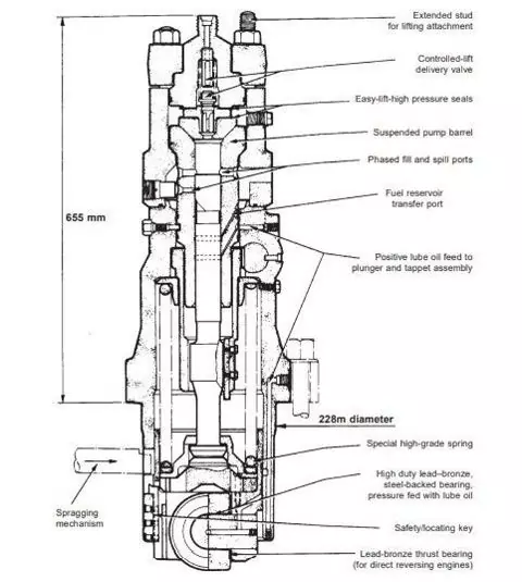
Operating Principles
A jerk-type pump is used to inject the fuel to combustion through in fuel valve in the Fuel injection system of a diesel engine. The pump consists of a plunger installed in the barrel, as illustrated in the image. Cam pushes the plunger in the upward direction with the help of a roller. The downward movement is achieved by the spring. The spring coil ensures constant contact between the cam follower cam profile and the plunger.
A rectangular vertically extends from top to the another helical groove. This helical groove controls the amount of fuel to be injected as per the requirement controlled by the governing system through the fuel control rod.
In the downward movement of the plunger, both the suction and spill ports are open, filling the barrel with fuel in the upward direction; pressure starts to build up as soon as the plunger covers the ports. The delivery valve is lifted from its seat due to the pressure of the fuel against the spring and allows the fuel to pass to the fuel valve through a High-pressure fuel pipe. Fuel injection continues till the plunger uncovers the spill cut-off port in its downward movement. The amount of fuel is controlled by the radial direction of the rotating plunger. The radial movement of the plunger with respect to the barrel is performed with the rack and pinion arrangement.
The distance between the pump plunger discharges to the end of discharge is known as Effective delivery stroke.
The injection timing can be altered by adding and removing the shims. An increase in shim will advance the fuel timing, and a decrease in shim will retard the fuel injection timing.
Advancing the fuel timing will cause the following advantageous changes in the Fuel injection system of diesel engine
- Increase in peak pressure
- Increase in thermal efficiency
- Increase in overall fuel efficiency.
A negative effect of advanced timing
- Excessive vibrations
- Shock engine loading.
Retardation in fuel timing will cause the negative effects only as under.
- Corrosion
- High Exhaust temperature
- After burning
- Low thermal efficiency
Adjustment of the Maximum Combustion Pressure
If the Fuel Injector, Inlet and exhaust valve, Piston, Turbocharger, and charge air cooler work in perfect condition. Compression pressure Pcomp is also well within the normal limits the Maximum combustion pressure will indicate the injection timing as per the following.
- Low Pmax will indicate the delayed timing
- High Pmax will indicate advanced timing
Injection timing is changed by adding or removing the shims from the bottom of the thrust piece above the roller guide. The measurement of “X” will be changed as per the above diagram.
Common Rail Injection System
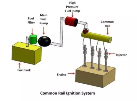
The common rail fuel injection system is the solid injection system. A constant pressure of 300 bars to 500 bars is maintained by a bypass valve on the main fuel header. Excess fuel is returned to the main fuel supply tank.
Operation of Common Rail injection
High pressure is supplied to a fuel header by a pimp. From the header, high-pressure fuel is forced to each injector fitted in cylinder heads. Fuel enters the cylinders at an appropriate time controlled by a mechanically operated mechanism.
The design of the header pressure must meet the requirements of the engine designed for the injector. The designed pressure must be able to penetrate droplets deep into the combustion chamber against the compression pressure. The amount of fuel entering the cylinder is regulated by the Solenoid valve operated by ECU. ECU transmits a signal to the injector to start injecting the fuel after receiving the signal from the crank angle sensor, scavenge air temperature, engine speed, Jacket water temperature, and the load. Standard rail system helps in reducing emissions, lower fuel consumption, and lower running speed. It helps in increasing combustion efficiency
Fuel Valve (Fuel Injector)
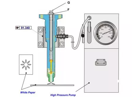
A fuel valve is installed in the cylinder head. A high-pressure fuel injection pipe connects the injector and high-pressure fuel pump in the jerk-type system and with the accumulator of the common rail fuel injection system. A nozzle with a multi-hole is installed in the valve, which operates against the pre-adjusted spring tension to achieve the correct injection pressure. Holes in the nozzle are closed by a needle valve under the pressure of the spring. The needle matches the proper seating angle at the valve seat, and a good bearing surface ensures the appropriate closing of holes.
Pressure in the injector chamber develops due to fuel at high pressure delivered to the injector In the delivery stroke of the Fuel injection pump. The increase in higher pressure more than the spring pressure of the injector needle valve is lifted, and the fuel is injected into the combustion chamber. After the fuel injection, the pressure in the fuel chamber gets reduced, and the spring shuts the needle back on its set. The spill causes a sudden drop in the high-fuel-pressure cut-off mechanism of the High-pressure fuel pump
Fuel valve tests
Criteria for the excellent performance of the fuel valves are listed below.
- Good atomization
- The correct spray pattern as the design of the combustion chamber ( by piston crown)
- No dribbling
- No leakage at the tip.
- Correct opening pressure.
Atomization
Fuel Atomization is when fuel is changed into droplet form by high-pressure injection Process of breaking the high pressure into small droplets and mixing these droplets with the compressed air for complete combustion. This process increases the surface area of the fuel droplets for better mixing of the air and fuel in a short amount of period.
Servicing of Fuel Valve
Dismounting and cleaning
- Remove the fuel injection valve from the cylinder head with the help of a special tool provided by the special tools for the engine.
- Use the clamping bracket for mounting the injector, and loosen the locknut (B). Release the stress of the nozzle spring by turning the screw D
- Before dismantling the nozzle nut (H), Clean the lower part of the nozzle (J) of carbon deposits.
- Take out the nozzle spring and the spring spindle by completely unscrewing the adjusting screw.
- Clean all parts with kerosene or gas oil and a stiff brush (not a steel brush).
- Use the special drill with holder to clean the nozzle holes of coke.
- Clean the cooling space in the injector body and nozzle guide. Blow them with air after cleaning.
- Insert the nozzle needle with gas oil in the needle guide. The nozzle needle should slide down by its weight.
- Check the nozzle holes for the wearing out in an oval pattern. This inspection is done using a magnifying glass.
All the defective parts found during the inspection must be replaced. If heavy abrasion symptoms, respectively damages are observed at the visual inspection of the parts, then replace the defective parts.
Reassembling
Assemble the fuel valve after careful cleaning, inspection, and overhaul, and find it in good order, then assemble the fuel injection valve. When building the injection valve, proceed in the opposite order compared to the disassembly.
Pay attention to the following: ( Fuel injection system of diesel engine )
- Lubricate the threads on the adjusting screw (D) with lubricating oil, and the threads of the nozzle holder for the nozzle nut
- Lubricate the shoulder of the nozzle, which is in contact with the nozzle nut with an anti-seize product.
- Wipe the plane sealing surface of the body and nozzle dry with paper.
- Renew the sealing rings (C) and (E).
- Tighten the nozzle nut as per the prescribed torque
Pressure testing of the fuel injection valve
The effective checking of the fuel valve is obtained through pressure testing of the valve.
The pressure testing is carried out in the following way using the pressure testing apparatus supplied
- Mount the fuel injection valve in the bracket by keeping the nozzle in a downward position.
- Mount the test pipe onto the stand for the test of the cooling oil system
Increase the pressure by the lever.
- Apply pressure to the cooling oil system after venting
- Check the sealing tightness of the O-ring
- Mount the test pipe for the test of the injection pressure and atomizing
- Adjust the opening pressure to 320 bar using the adjusting screw (D), see fig 2, then tighten the locknut (B)
- Recheck opening pressure.
Do not expect to chatter, but ensure that the nozzle spray from all holes is at the same angle.
- Raise the pressure to 300 bar and hold the pressure moving the lever handle slowly downward.
There should not be more than one drip from the nozzle tip for a period of 3 to 5 secs at 300 bar pressure
Following tests are conducted on the fuel valves for the best performance
Spray pattern test
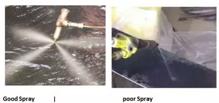
This test will indicate the uniformly and properly atomized spray of fuel through all the holes. The impression of atomization can be taken on a blotting paper kept at the specified distance as per the height at which the injection takes place in the combustion chamber and the crank angle for the injection timing.
Spray Pressure
The spray should occur from 320 Barto350 Bar; if the pressure is down than the specified pressure limit, then the nozzle should be re-adjusted/changed. Pressure is adjusted by decreasing or increasing the tension of the nozzle spring.
Fuel in the mist form is injected by the fuel injector. During the initial phase of combustion, Oxidisation of the small droplets starts. Combustion will be efficient and at a very fast rate with these smaller droplets.
It is a trend in high-injection pressure modern engines to use smaller droplets and finer spray.
During efficient combustion, droplets burn out perfectly before they approach the cylinder liner. The fuel is sprayed in the combustion chamber formed between the piston crown and Cylinder cover. During the downward movement of the piston, the spray penetrates further into the area of the combustion chamber and burns out before any droplet reaches to cylinder walls.
However, if the spray pattern produced by the fuel injector is not in conformity with the above description, droplets enlarge to a bigger size and delay in burnout.
Effects of Poor Spray Pattern
The following phenomenon takes place due to the poor spray pattern.
Oil film will be destructed from the working surface of cylinder liners and will lead to dry rubbing of pistons and piston rings on the cylinder liner walls. Due to the nonavailability of lubricating oil, the coefficient of friction increases developing excess heat. Due to the excess heat piston will have seizures and ultimately lead to failure.
Dribbling
The perfectly working nozzle will have a dry nozzle tip. No leakage is accepted before and after the injection. Checking the dribbling is by having injections manually done several times quickly and inspecting the nozzle tip for any leakage. Raising the pressure within 10 to 15 bars and holding it for about 10 seconds will also give a clear idea.
In the event of the needle tip not seating properly in its seat, fuel will drip from the nozzle tip wetting the surface of the piston crown. In such a situation, combustion will directly take place locally at the crown resulting in melting away of the piston crown.
The reason for the nozzle dribbling is
- Improper pressure setting
- Dirt stuck up between the needle and valve seat.
- Inappropriate contact between needle and needle seat.
- Needle sticking in the body.
Nozzle leak-off rate
A significantly less amount of fuel for the lubrication passes inside between the needle and the valve body. Excess clearance between the needle and the valve body will cause a leak and will reduce the amount of fuel supplied for the combustion.
Blog Conclusion
In conclusion, it is critical for maritime engineers to comprehend the fuel injection system.
This part of the engine ensures fuel is delivered properly.
Understanding how the fuel injection parts work can help make engines more efficient and decrease emissions. So, keep exploring and stay curious!
FAQ on ” Fuel Injection System
Q: What is a fuel injection system?
A: A fuel injection system is a mechanism that delivers fuel to an engine for combustion.
Q: What are the components of a fuel injection system?
A: Components include injectors, pumps, sensors, and control units
Q: How does the system work?
A: It sprays fuel directly into the engine cylinders.
Q: What are the benefits?
A: Better fuel economy, reduced emissions, and smoother-running engines.
