Table of Contents
How Does A Gas Powered Engine Work
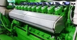
A Gas Powered Engine in the maritime world refers to marine gas engines and gas-powered diesel generators, which are crucial for powering various types of vessels and offshore platforms. These engines are tailored to handle the unique challenges of marine environments, ensuring reliable and efficient operation. In this blog post, we’ll dive into the world of marine gas engines used mainly for ship propulsion, designed to endure the tough conditions at sea and offer superior fuel efficiency.
We’ll also explore gas-powered diesel generators that provide essential auxiliary power for onboard electrical systems, keeping critical operations running smoothly. Both types of engines play a significant role in enhancing maritime operations’ efficiency and sustainability, especially as the industry shifts towards cleaner energy solutions like LNG. Join us as we unpack the benefits and advancements of gas-powered engines and generators in the marine sector, highlighting their contribution to modern maritime activities.
How Does a Gas Engine Work
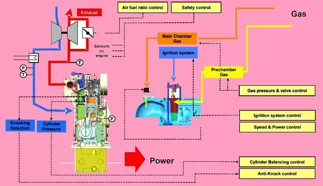


The engine fuel gas which is regulated by the external gas system is supplied to the two gas rails for the chambers and main chambers of each cylinder. The rich gas is injected into the chamber via the check valve which is actuated by the cam mechanism and the injected gas is burned by the ignition device in the chamber. Flames in the chamber efficiently cause combustion in the cylinder with main gas which is supplied from the gas admission valve into the intake of cylinder with air.
Key Components of a Gas Engine
A gas engine comprises several crucial components working in harmony. These include the fuel system, intake and exhaust valves, cylinders, pistons, spark plugs, and the exhaust system. Each part plays a pivotal role in the engine’s performance.
Internal Fuel Gas System
Gas Admission Valve
The gas admission valve releases the gas into the air intake of the cylinder head. It is controlled electronically by the engine control system to regulate engine speed and power. It is normally closed by a spring, but when there is the electronic signal it is opened with suitable timing and duration. That makes it possible to control the amount of gas fed to each cylinder for speed and load balancing of the engine.
Check valve
The check valve in the chamber is controlled by the spring-loaded linkage via camshaft moving. It is sealed closely with several O- O-rings. If it has any leakage gas, it releases the gas through the vent line for safety.
Venting valve
The venting valve purges the gas from the main gas feed rails. The valve is actuated pneumatically and controlled by ECS when the engine stops the condition
External Fuel Gas System
The gas supply to the engine, it passes through the external fuel gas system in order to ensure safe operation to maintain the desired pressure in the rails for the main gas feed and precharge gas feed. The external fuel gas system adjusts the gas pressure via the pneumatic regulator which is controlled by the engine control system.
Gas filter
The gas filter protects the downstream equipment of a pressure regulator from impurities such as dust, rust, and other solid particles. It fills out the particles of 2um and over, and the filtration degree is 99%.
Flow meter
The flow meter directly measures the flow rate at measurement conditions and integrates the measured values. As a result, the gas volume that flows through the meter is registered by an electronic totalizing unit.
Double block valves
Double block valves cut off the gas supply to the engine when the engine is not running or in an emergency. The two valves are activated by an electronic signal from the engine control system. When the signal is switched on (or off), they are opened (or closed) automatically. After the double-block valves are closed, the gas venting valves are opened immediately and de-pressurizes the gas train unit. That makes the gas-blocking operation more effective and safe.
Gas pressure regulator
The gas pressure regulator adjusts the gas feed pressure to the setpoint and keeps independent of disturbing influences like inlet pressure or flow rate changes. It is controlled by the engine control system via an I/P-converter, which transforms the computed electronic signal into the control air pressure.
Internal Lubricating Oil System
The engine has its own Internal Lubricating Oil system with wet type oil sump, which supplies lubricating oil to all moving parts for lubricating as well as for cooling.
Most of the oil passages are incorporated into the engine components and the equipment of the system is mounted directly on the Feed Module without pipe connections.
Engine-Driven Lubricating Oil Pump
The engine-driven lub. oil pump is a gear type, mounted on the feed module of the engine. The pump is designed to provide sufficient flow even at low speeds.
Pre-lubricating Oil Pump
The pre-lubricating pump is an electric motor-driven gear type and this is operated automatically when the engine is stopped. Pre-lubrication is recommended during the engine stop period if ready to start condition.
Lubricating Oil Cooler
The lubricating oil cooler is plate type, mounted on the feed module of the engine.
Thermostatic Valve
The thermostatic valve is the wax element type, working at a fixed temperature range of 60 -69℃, and this is mounted on the feed module of the engine
Lubricating Oil Filter
The lubricating oil filter is an automatic filter type, mounted on the feed module of the engine. Each filter has a Full-flow chamber and diversion chamber.
Full-flow chamber fitness: 34㎛ –
Diversion chamber fitness: 34㎛
Pressure Regulating Valve
The pressure regulating valve adjusts inlet pressure after lube. oil filter at 4~5 bar and is mounted on the feed module of the engine.
Centrifugal Oil Filter (Option)
A centrifugal oil filter can be mounted on the engine. The centrifugal force is taken from the oil pressure.
Lubricating oil sump drain
It is recommended to use the separator suction pipe for draining the lubricating oil sump.
External Lubricating Oil System
The external lubricating oil system is required not only for cleaning but also for heating the oil to start the engine quickly. The system may be used commonly for all auxiliary engines.
Though filtering equipment built on an engine may be sufficient for the engine operating on Gas or MDO, centrifugal purification is commonly required for the engine operating on MDO and HFO.
Lubricating Oil Separator
Self-cleaning type or manual cleaning type separators can be used.
Overflow system
In some cases, an overflow system can be applied as an alternative for continuous purification.
In order to have a better siphon effect, the overflow pipe from the sump to the overflow tank should have a continuous downward gradient of a minimum of 10 degrees without a high and low point.
Suction Strainer
0.8 ~ 1.0 mm mesh size of suction filter should be inserted before the separator pump.
Pump for separator
The pump can be either directly driven by the separator or driven by an independent motor as recommended by a separator maker.
Heater for separator
The lubricating oil in the wet sump tank and in the system is to be warm-up to 40 ℃ from the separator heater prior to the engine starting. The sump tank is to be heated up to approx 65 ℃ in engine service.
The heater for the separator should be designed to heat the lubricating oil from 65 ℃ up to 95 ~ 98 ℃ according to the separator maker’s recommendation.
If the separation temperature is lowered from 95 ℃ to 90 ℃ the separator throughput has to be reduced by 22% to maintain the same separation efficiency.
Internal Cooling Water System
The engine has two cooling water circuits internally, which are low-temperature (LT) and high-temperature (HT) water circuits.
Most of the elements of the circuits are modularized and directly mounted on the Feed Block.
Low-temperature water circuit
The low-temperature water system is for machinery that needs cooler temps. It’s linked to the main seawater cooler, so it’s colder than the high-temperature system. This low-temp setup includes extra systems for proper cooling. The amount of low-temp water is balanced with the high-temp system using an expansion tank. This tank is filled from the hydrophore or distilled water tank via the refilling pump.
High-temperature water circuit
The high-temperature water system is like a cooling team for the central setup. It’s essential for the main engine, which can get super hot. In this system water temperature is maintained by use of colder water. It’s also needed for the FW generator, standby DG, and lube oil filter. Electric pumps move the warm water around, and there’s a backup pump just in case. When the main engine stops, the standby DG stays warm with the circulating water. If needed, they can use steam to make the water even hotter.
Engine Control Gas System
Engine Control gas consists of the following controls.
Speed & Power control:-
The engine control system adjusts the amount of gas injection by regulating the duration of gas admission valve for speed and power control.
Air Fuel Ratio Control
Opening of Waste-gate ratio will control the air-fuel ratio. The wastegate controls the amount of bypassed exhaust gas to the Turbocharger. The charge air pressure at each load point will decide the operation point.
Ignition system Control
The spark plug in the pre-combustion chamber is the ignition source of combustion. The engine control system controls the precise ignition timing and energy of the ignition system
Gas Pressure and Valve Control
The engine control system manages the control of gas pressure regulation, sequential gas valve operation, and the operation of gas admission valve.
Cylinder Balancing and Knocking Control
The gas engine control system is integrated with knock detection and monitoring of cylinder pressure. The engine control system transmits the pressure and knocking signals to the pane.
Engine Control System Overview
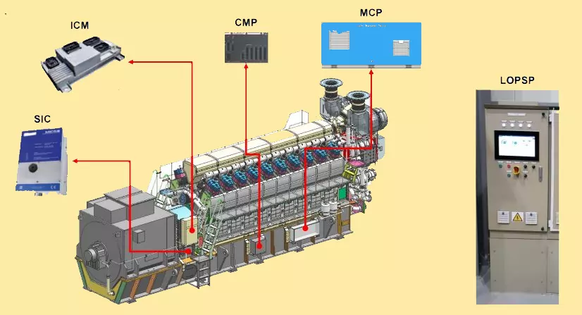


Introduction;- The Diesel Gas Engines power plants consist of the following systems.
- Engine Control system
- Engine generator control panel
- Plant control and monitoring system
All the above systems are interfaced through Ethernet.
System Overview
The engine control system consists of the following panels and modules.
- Main Control panel
- Injection control module
- Spark ignition control module
- Cylinder Monitoring Panel
- Local operating and Power supply panel.
Main Control panel
The main control panel is mounted on the Engine and consists of the following controls.
- The main control of Gas
- Engine safety control
- Engine shutdown control
- Governor control
- Gas regulating unit control
- Cooling water valves control
- Air fuel ratio control Waste –gate
- Interface with LOSP (local operating and power supply panel) and Engine generator control panel.
Injection Control Module
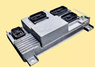


ICM (Injection control module) is mounted on the engine and connected with the Gas admission valves and exhaust sensors temperature on each cylinder unit. The functions of the ICM are listed below.
- Drives the gas admission valve
- Measures the exhaust gas temperature
- Transmits the data to a main control panel via CAN communication.
Cylinder monitoring panel
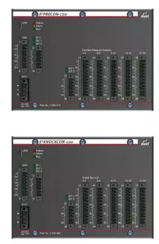


CMP monitors the combustion characteristics and intensity of knock at each cylinder & communicates the information with the main control panel for monitoring and control of Diesel Gas Engines
CMP’s location is on Engine. CMP performs the following functions.
- Cylinder pressure signal measurement
- Process and measurement of knock signal
- Combustion characteristic calculation
- Calculation of knock characteristic
- Transmission of data to the main control panel
Local Operating and Power supply panel
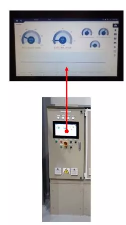


Operators use this panel mounted in self standing cabinet for the local operation and monitoring of the engine.
LOSP performs the following functions on Diesel Gas Engines
- Local operation for starting, stopping, and resting of alarms on the engine.
- Display of Engine measurement and status.
- Display of alarms
- Display of events
- Test of actuators and valves in engine stop mode.
- Power distribution control to MCP, ICM, SIC, CMP
Interface with the main control panel
Engine Generator Control panel
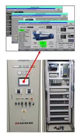


The engine generator control panel for Diesel Gas Engines is installed in the control room as a self-standing cabinet. The main functions of EGCP are as under.
- Remote operation for starting, stopping, and resting of alarms.
- Voltage control with the help of AVR.
- Opens and closes the generator circuit breakers.
- Emergency stopping of the engine. Safety control and protection of the engine.
- Synchronization on auto and manual mode.
- Selection of power control mode.
- The setting of demand power.
- Engine and Generator measurement display.
- Display of electrical parameters.
- Displaying of alarm and events.
- Interface with plant control monitoring system
Monitoring and Plant control system
PCMS is installed in the control room. PCMS consists of Station PLC and operation station. PCMS controls and monitors the Engine and generator set.
The functions of PCMS are as under.
- Remote operation
- Auto or manual operation
- Emergency stop of engine
- Auto synchronization
- Section of power control mode.
- The setting of power demand
- Engine and generator status display
- Display of electrical parameters
- Auxiliary equipment and switchgear display
- Tank level display
- Display of Alarms
- Trending
Future Trends in Gas Engine Development
As technology evolves, gas engines continue to improve. Advancements in materials, design, and hybrid integration are shaping the future of internal combustion engines, making them more efficient, powerful, and environmentally friendly.
Which fuel is used in gas engines?
Gas engines use a type of fuel known as “natural gas.” It’s a cleaner and more environmentally friendly option compared to other fuels. Natural gas is made up of gases found deep in the ground, and it’s used to power these engines and make them work. It’s a bit like the food that gives us energy but for engines!
What’s the difference between diesel and gas engines?
The big difference between diesel and gas engines is how they make power. Gas engines use a spark from a plug to light up gasoline and air. But in diesel engines, there’s no spark – instead, the pressure from compressing air makes the diesel fuel burn. That’s why diesel engines don’t need spark plugs like gas engines do.
Conclusion
Gas engines are intricate powerhouses that convert fuel into the kinetic energy that propels our vehicles. Understanding their components and processes gives us insight into the incredible engineering behind every drive. Whether it’s harnessing explosions, managing airflow, or optimizing combustion, the gas engine’s capabilities are truly remarkable.
FAQs (Frequently Asked Questions)
Q: How does a spark plug create a spark?
A: Spark plugs use electrical energy to create a spark across a gap, igniting the fuel-air mixture in the cylinders.
Q: What is the advantage of variable valve timing?
A: Variable valve timing optimizes engine performance by adjusting valve opening and closing timing for different driving conditions.
Q: Can hybrid engines operate without gasoline?
A: Yes, hybrid engines can operate on electric power alone at lower speeds, reducing the need for gasoline
Q: Are turbochargers and superchargers the same?
A: They both increase engine power, but turbochargers are powered by exhaust gases, while superchargers are driven by the engine’s crankshaft.
Q: What does the future hold for gas engines?
A: Gas engines will continue to evolve with advancements in materials, design, and hybrid technology, aiming for higher efficiency and reduced emissions.
